


241
CHAPTER 10 EXTERNAL INTERRUPT CIRCUIT 1 (EDGE)
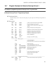
10.7 Program Example for External Interrupt Circuit 1
An example of programming external interrupt circuit 1 is given below.
■ External Interrupt Circuit 1 Programming Example
● Processing specification
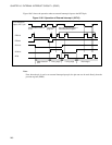
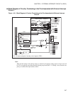
External interrupt circuit 1 detects the rising edge of a pulse input to the INT10 pin and generates an
interrupt.
● Coding example
DDR3 EQU 000DH ; Address of port data direction register (DDR)
EIC1 EQU 0024H ; External interrupt control register 1
TCR2 EQU 0020H ; Address of 8/16-bit capture timer output control
register
ILR1 EQU 007BH ; Setting of interrupt level setting register 1
EIR0 EQU EIC1:3 ; Definition of external interrupt request flag bit
SL01 EQU EIC1:2 ; Definition of edge polarity selection bits
SL00 EQU EIC1:1 ; Definition of edge polarity selection bits
EIE0 EQU EIC1:0 ; Definition of interrupt request enable bit
INT_V DSEG ABS ; [DATA SEGMENT]
ORG 0FFFAH
IRQ1 DW WARI ; Interrupt vector (INT1) setting
INT_V ENDS
;------------------------Main program--------------------------------------------------------------------------------
CSEG ; [CODE SEGMENT]
; Stack pointer (SP) is assumed to have been initialized.
: ;
CLRI ; Disable interrupts.
CLRB EIR1 ; Clear external interrupt request flag.
MOV TCR2,#00000000B ; Set pin P34/TO/INT10 to serve port inputs.
MOV DDR3,#00000000B ; Set P34 to serve inputs only.
MOV ILR1,#11111110B ; Set interrupt level at 2.
CLRB SL01 ; Select rising edge.
SETB SL00 ;
CLRB EIR0 ; Clear external interrupt request flag.
SETB EIE0 ; Enable interrupt request outputs.
SETI ; Enable interrupts.
:
;------------------------Interrupt processing routing----------------------------------------------------------------
WARI CLRB EIE0 ; Clear external interrupt request flag (INT0).
PUSHW A
XCHW A,T