


236
CHAPTER 10 EXTERNAL INTERRUPT CIRCUIT 1 (EDGE)
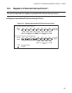
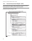
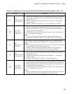
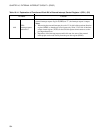
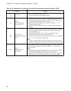
Table 10.4-2 Explanation of Functions of Each Bit in External Interrupt Control Register 2 (EIC2)
Bit name Function
bit7
to
bit4
Unused bits
• Bit value is undefined when being read.
• Written value does not affect other operations.
bit3
EIR2:
External interrupt
request flag bit 2
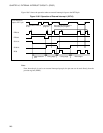
• When a signal with an edge or edges corresponding to edge polarity
selected by edge polarity selection bits 2 (SL21, SL20) is input to the
INT12 external interrupt pin, this bit is set to "1".
• When this bit and interrupt request enable bit 2 (EIE2) are "1", the
interrupt request is output.
• Writing "0" clears this bit, and writing "1" does not affect this bit (no
change).
bit2
bit1
SL21, SL20:
Edge polarity selection
bits 2
• These bits are used to select the polarity of an edge or edges of a signal
pulse that triggers an interrupt when the signal is input to the INT12
external interrupt pin.
• When these bits provide a value of "00
B
", edge detection is not
performed and interrupt requests are not generated.
• These bits may specify "01
B
", indicating a rising edge, "10
B
", a falling
edge, or "11
B
", both edges to be detected.
Note:
If edge is selected while edge detection is OFF, edge detection may be
performed unconditionally. Always clear EIR2 bit after selecting an edge.
bit0
EIE2:
Interrupt request
enable bit 2
This bit enables or disables interrupt request outputs to the CPU. When this
bit and external interrupt request flag bit 2 (EIR2) are "1", the interrupt
request is output.
Notes:
• When using the external interrupt pin, write "0" for bit6 of the port data
direction register (DDR3) so that the pin serves inputs only.
• Regardless of the interrupt request enable bit state, the state of external
interrupt pin can be read directly from the port data register (PDR3).