5
CHAPTER 1 OVERVIEW
Note:
The oscillation is 12.5 MHz unless another condition such as the main clock maximum speed, the clock
cycle value, or conversion time is stated.
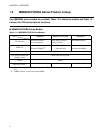
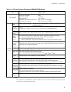
Table 1.2-2 CPU and Peripheral Functions of MB89202/F202RA Series
Item Specification
CPU function
Number of basic instructions: 136 instructions
Instruction bit length: 8 bits
Instruction length: 1 to 3 bytes
Data bit length: 1, 8, or 16 bits
Minimum instruction execution time: 0.32 to 5.1 µs (at 12.5 MHz)
Interrupt processing time: 2.88 to 46.1 µs (at 12.5 MHz)
Periphera
l function
Port
General-purpose I/O port: 26 pins (Also serve as peripherals. 4 of which can be used as N-ch
open-drain I/O ports.)
21-bit
time-base
timer
21 bits
Interrupt cycle: 0.66 ms, 2.64 ms, 21 ms, or 335.5 ms with 12.5MHz main clock
Watchdog
timer
Reset occurrence cycle: When the main clock is at 12.5 MHz (minimum 335.5 ms)
8-bit
PWM
timer
8-bit interval timer operation (Square wave output is supported. Operating clock cycle:
1 t
INST
, 16 t
INST
, 64 t
INST
, and 8/16-bit capture timer/counter output)
8-bit resolution PWM operation (Conversion cycle:
256 t
INST
, 4096 t
INST
, 16384 t
INST
and 256 times 8/16-bit capture timer/counter output)
8/16-bit
capture
timer/
counter
8-bit capture timer/counter × 1 channel + 8-bit timer or 16-bit capture timer/counter × 1 channel
When timer 0 or a 16-bit counter is operating, event-counting operation by external clock input
and square wave output are supported.
UART Transfer data length: 6, 7, or 8 bits
8-bit serial
I/O
8 bits length, LSB first/MSB first selectability
One clock selectable from four operation clocks
(one external shift clock, three internal shift clocks: 2 t
INST
, 8 t
INST
, 32 t
INST
)
12-bit
PPG timer
Output frequency: Pulse width and cycle are selectable.
External
interrupt 1
(wake-up)
3 channels (interrupt vector, request flag, and request output enable)
Edge selectability (selectable from rising edge, falling edge, and both-edge modes)
Also available for wake-up from stop or sleep (Edge detection is also available in stop mode.)
External
interrupt 2
(wake-up)
8 inputs 1 channel (L level interrupt and input enable are independent.)
Also available for wake-up from stop or sleep (Level detection is also available in stop mode.)
10-bit A/D
converter
10-bit resolution × 8 channels
A/D conversion function (Conversion time: 38 t
INST
)
Continuous activation by 8/16-bit capture timer/counter output or time-base timer output.
Wild
register
8-bit × 2


