13
CHAPTER 1 OVERVIEW
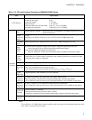
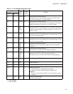
17 18 P32/UI/
SI
B General-purpose CMOS I/O ports.
This pin also serves as the data input pin for the UART or 8-bit
serial I/O. The resource is a hysteresis input.
15 15 P33/EC B General-purpose CMOS I/O ports.
This pin also serves as the external clock input pin for the 8/16-bit
capture timer/counter. The resource is a hysteresis input.
14 14 P34/
TO/
INT10
B General-purpose CMOS I/O ports.
This pin also serves as the output pin for the 8/16-bit capture timer/
counter or as the input pin for external interrupt 1. The resource is a
hysteresis input.
13 13 P35/
INT11
B General-purpose CMOS I/O ports.
These pins also serve as the input pin for external interrupt 1. The
resource is a hysteresis input.
12 12 P36/
INT12
B General-purpose CMOS I/O ports.
These pins also serve as the input pin for external interrupt 1. The
resource is a hysteresis input.
11 11 P37/
BZ/
PPG
E General-purpose CMOS I/O ports.
This pin also serves as the buzzer output pin or the 12-bit PPG
output pin.
20 21 P50/
PWM
E General-purpose CMOS I/O ports.
This pin also serves as the 8-bit PWM timer output pin.
24 to 27 26 to 29 P40/
AN0 to
P43/
AN3
F General-purpose CMOS I/O ports.
These pins can also be used as N-ch open-drain ports.
These pins also serve as 10-bit A/D converter analog input pins.
21 to 23 23 to 25 P70 to
P72
E General-purpose CMOS I/O ports.
32 34 V
CC
-- Power supply pin
10 10 V
SS
-- Power (GND) pin
16 17 C -- MB89F202/F202RA:
Capacitance pin for regulating the power supply.
Connect an external ceramic capacitor of about 0.1µF.
MB89202:
This pin is not internally connected. It is unnecessary to connect
a capacitor.
-- 16, 22 N.C. -- Internally connected pins
Be sure to leave it open.
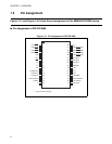
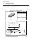
*1 : DIP-32P-M06
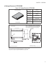
*2 : FPT-34P-M03
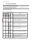
Table 1.7-1 Pin Functions Description (2/2)
Pin No.
Pin
name
Circuit
type
Function
SHDIP32
*1
SSOP34
*2


