


335
CHAPTER 14 8-BIT SERIAL I/O
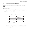
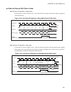
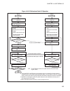
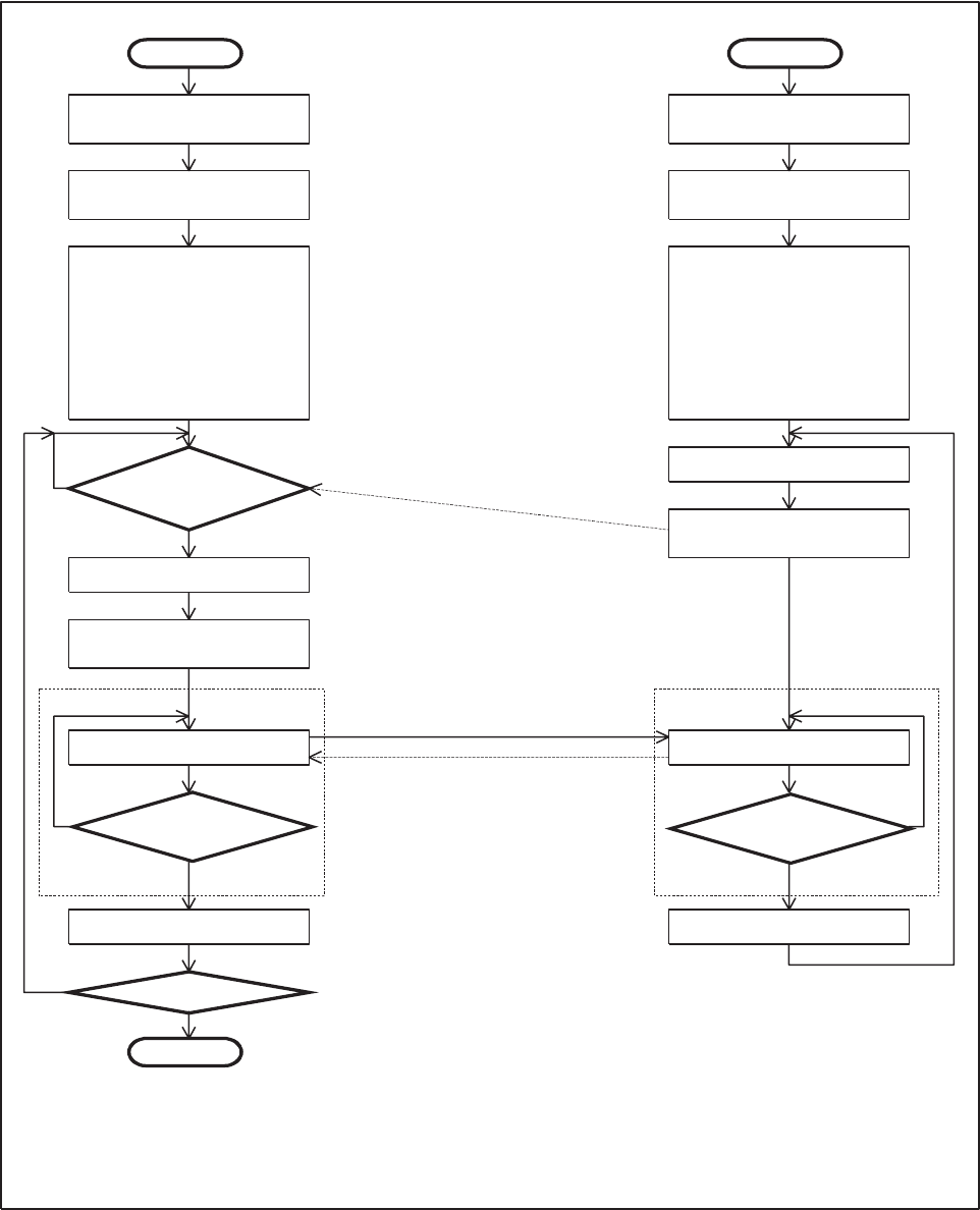
Figure 14.10-2 Bidirectional Serial I/O Operation
(SST=0)
(SST=1)
SIO-A
YES(SST=0)
END
YES(SST=0)
SIO-A
NO NO
SIO-B
NO
YES
SIO-B
START STA RT
(SST=0)
(SST=1)
NO
YES
Stop SIO-A operation
Set SI pin to serial data
input (input port)
Set SCK pin to shift clock
output
-
Set data transfer (shift
clock) direction
-
-
Set SO pin to serial data
output
-
Select internal shift clock
Is SIO-B in
serial transfer allowance
state?
(*1)
Transfer allowance state
Set output data
Start serial I/O transfer
(*2)
Serial data transfer
Serial data output via SIO-A
Simultaneous data input via SIO-B
End of 8-bit transfer?
(*3)
Read input data
Is next data available?
Stop SIO-B operation
Set SI pin to serial data
input (input port)
-
-
-
-
Set SCK pin to shift clock
input
Set SO pin to serial data
output
Select external shift clock
Select same data transfer
(shift) direction as SIO-A
Allow serial data transfer
Set output data
Serial data transfer
End of 8-bit transfer?
(*3)
Read input data
The SST bit is the serial I/O transfer start bit of the serial mode
register (SMR).
SST:
*1
*2
*3
If only the SO, SI, and SCK pins are connected, there is no method for directly checking
whether SIO-B is in the serial transfer allowance state. For this reason, a timer, etc., must be
used to monitor the wait time period that lasts until SIO-B is allowed for tra
nsfer via software.
If SIO-B is not allowed for serial I/O transfer, data cannot be transferred correctly even if
SIO-A starts serial I/O transfer.
When 8-bit data transfer terminates, a interrupt request occurs.