336
CHAPTER 14 8-BIT SERIAL I/O
14.11 Program Example for 8-Bit Serial I/O
This section provides program example for 8-bit serial I/O.
■ Program Example for 8-bit Serial Output
● Processing Specifications
• The 8-bit serial output program outputs 8-bit serial data (55
H
) from the SO pin of the 8-bit serial I/O.
When serial I/O transfer terminates, an interrupt occurs.
• The program resets transfer data with the interrupt processing routine and outputs it continuously.
• The program operates in accordance with the internal shift clock. This clock is output from the SCK
pin.
• If the shift clock is 32t
INST
when the maximum gear speed (1 instruction cycle = 4/F
CH
) at the 12.5-
MHz oscillation (F
CH
), the transfer rate and interrupt cycle are as follows:
Transfer rate = 12.5 MHz/4/32 = 97.7 kbps, interrupt cycle = 8 × 32 × 4/10 MHz = 81.92 µs
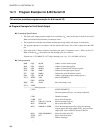
● Coding example
SMR EQU 0039H ; Address of serial mode register
SDR EQU 003AH ; Address of serial data register
SSEL EQU 003BH ; Address of serial/UART selection register
SIOF EQU SMR:7 ; Defines the interrupt request flag bit.
SST EQU SMR:0 ; Defines the serial I/O transfer start bit.
ILR4 EQU 007EH ; Address of interrupt request setting register 4
INT_V DSEG ABS ; [DATA SEGMENT]
ORG 0FFE2H
IRQC DW WARI ; Sets an interrupt vector.
INT_V ENDS
;--------------------Main program--------------------------------------------------------------------------
CSEG ; [CODE SEGMENT]
; The stack pointer (SP), etc., are already initialized.
:
CLRI ; Disables interrupts.
CLRB SST ; Stops serial I/O transfer.
MOV ILR4,#11111101B ; Sets the interrupt level to 1.
MOV SDR,#55H ; Sets transfer data (55H).
MOV SMR,#01111000B ; Clears the interrupt request flag, allows the interrupt
request output, shift clock output (SCK), and serial data
output (SO), selects 32tINST, and sets LSB first.
MOV SSEL,#00000001B ; Selects the 8-bit serial I/O.
SETB SST ; Starts serial I/O transfer.
SETI ; Enables interrupts.
:


