


63
CHAPTER 3 CPU
3.7.1 Operations in Standby Mode
This section describes CPU and peripheral function operation in standby mode.
■ Operations in Standby Mode
● State of pins in standby mode
The state of most I/O pins can remain the same as those set immediately before transition to stop mode or
set to Hi-Z using the pin state setting bit in the standby control register (STBC: SPL), regardless of clock
mode.
Note:
For details on pin states in standby mode, see "APPENDIX E Pin State of the MB89202/F202RA
Series ".
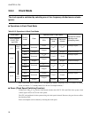
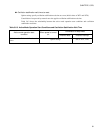
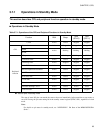
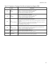
Table 3.7-1 Operations of the CPU and Peripheral Functions in Standby Mode
Function RUN Sleep
Stop
(SPL=0)
Stop
(SPL=1)
Clock Active Active Stopped Stopped
CPU
Instruction Active Stopped Stopped Stopped
ROM
Active Holding Holding Holding
RAM
Peripheral
function
I/O port Active Holding Holding Hi-Z
Time-base timer Active Active Stopped Stopped
Watchdog timer Active Stopped Stopped Stopped
8-bit PWM timer/counter Active Active Stopped Stopped
8/16-bit capture timer/counter Active Active Stopped Stopped
UART Active Active Stopped Stopped
8-bit serial I/O Active Active Stopped Stopped
12-bit PPG Active Active Stopped Stopped
Buzzer Active Active Stopped Stopped
External interrupt 1 and 2 Active Active Active Active
A/D converter Active Active Stopped Stopped