


228
CHAPTER 10 EXTERNAL INTERRUPT CIRCUIT 1 (EDGE)
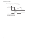
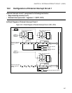
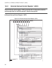
● Edge detecting circuits
When the edge polarity of a signal input to one of the pins (INT10 to INT12) for external interrupt circuit 1
matches the selected edge polarity for the pin, stored in either the EIC1 or EIC2 registers in the appropriate
bit position (SL00 to SL21), one of the external interrupt request flag bits (EIR0 to EIR2) corresponding to
the pin is set to "1".
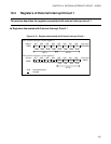
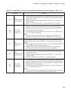
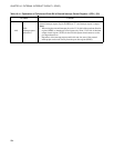
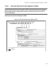
● External interrupt 1 control registers (EIC1, EIC2)
The EIC1 and EIC2 registers comprise bits for edge selection, for enabling or disabling interrupt requests,
and for confirming an interrupt request.
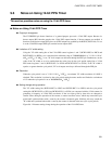
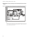
● Triggers that cause external interrupt circuit 1 to generate an interrupt request
• IRQ0: When a signal with an edge or edges corresponding to the selected edge polarity is input to the
INT10 pin for external interrupt circuit 1, if interrupt request outputs are enabled (EIC1:EIE0=1),
external interrupt circuit 1 generates an IRQ0 interrupt request.
• IRQ1: When a signal with an edge or edges corresponding to the selected edge polarity is input to the
INT11 pin for external interrupt circuit 1, if interrupt request outputs are enabled (EIC1:EIE1=1),
external interrupt circuit 1 generates an IRQ1 interrupt request.
• IRQ2: When a signal with an edge or edges corresponding to the selected edge polarity is input to the
INT12 pin for external interrupt circuit 1, if interrupt request outputs are enabled (EIC2:EIE2=1),
external interrupt circuit 1 generates an IRQ2 interrupt request.