


36
CHAPTER 3 CPU
3.4.1 Interrupt Level Setting Registers (ILR1 to ILR4)
For the interrupt level setting registers (ILR1, 2, 3, and 4), 16 two-bit data items
corresponding to interrupt requests sent from peripheral functions are assigned.
Interrupt levels can be specified in these 2-bits (interrupt level setting bits).
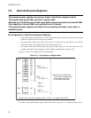
■ Configuration of the Interrupt Level Setting Registers (ILR1 to ILR4)
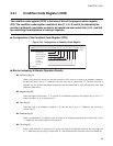
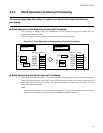
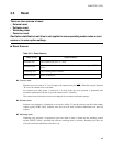
Figure 3.4-1 Configuration of Interrupt Level Setting Register
For each interrupt request, 2 bits of the interrupt level setting registers are assigned. The values specified in
the interrupt level setting registers are the intensities for processing the interrupts (interrupt levels 1 to 3).
Interrupt level setting bits are compared with interrupt level bits in the condition code register (CCR: IL1
and IL0).
When interrupt level 3 is specified, the CPU does not accept interrupt requests.
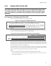
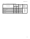
Table 3.4-2 provides the relationship between interrupt level setting bits and interrupt levels.
Notes:
• When the main program is being executed, the interrupt level bits in the condition code register
(CCR: IL1 and IL0) are normally set to 11
B
.
• The ILR1 to ILR4 registers are write-only enabled, and thus the bit manipulation instructions (SETB
and CLRB) cannot be used.
bit7 bit6 bit5 bit4 bit3 bit2 bit1 bit0
ILR1 007B
H
L31 L30 L21 L20 L11 L10 L01 L00 1111 1111
B
(W) (W) (W) (W) (W) (W) (W) (W)
ILR2 007C
H
L71 L70 L61 L60 L51 L50 L41 L40 1111 1111
B
(W) (W) (W) (W) (W) (W) (W) (W)
ILR3 007D
H
LB1 LB0 LA1 LA0 L91 L90 L81 L80 1111 1111
B
(W) (W) (W) (W) (W) (W) (W) (W)
ILR4 007E
H
LF1 LF0 LE1 LE0 LD1 LD0 LC1 LC0 1111 1111
B
(W) (W) (W) (W) (W) (W) (W) (W)
W: Write only
Register Address (Initial value)
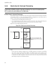
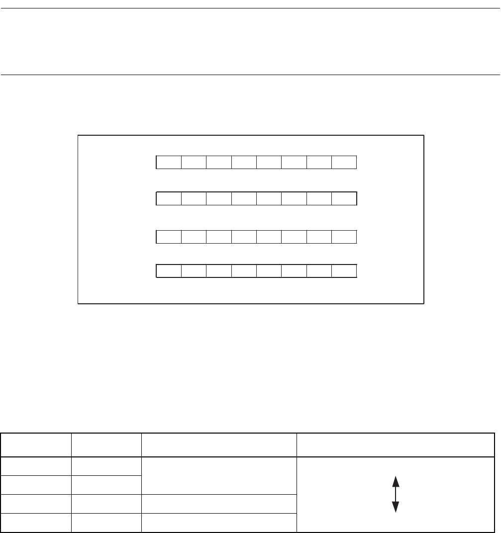
Table 3.4-2 Relationship between Interrupt Level Setting Bits and Interrupt Levels
L01 to LF1 L00 to LF0 Requested interrupt level Priority
00
1
High
Low (no interrupt)
01
10 2
11 3