


311
CHAPTER 13 UART
13.7 Program Example for UART
This section provides program example for UART.
■ Program Example for UART
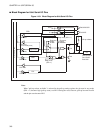
● Program specifications
• Serial data transfer is implemented using the UART communication functions.
• The P30/UCK/SCK, P31/UO/SO, and P32/UI/SI pins are used for communication.
• The transfer rate is set to 300 bps using the internal baud rate generator.
•13
H
is transmitted from the UO pin, and data is received by interrupts.
• The baud rate is the oscillation frequency (F
CH
= 12.5 MHz) at the maximum gear speed (1 instruction
cycle = 4/F
CH
). The clock divider is 2.5. (1/375 bps = 8320 t
INST
)
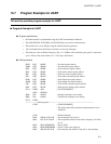
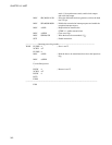
● Coding example
PDR3 EQU 000CH ; Port data register address
DDR3 EQU 000DH ; Port direction register address
SSEL EQU 003BH ; Serial selection register address
SMC EQU 0028H ; Serial mode control register address
SRC EQU 0029H ; Serial rate control register address
SSD EQU 002AH ; Serial status and data register address
SIDR EQU 002BH ; Serial input data register address
SODR EQU 002BH ; Serial output data register address
UPC EQU 002CH ; Clock divider selection register address
ILR2 EQU 007CH ; Interrupt level setting register address
INT_V DSEG ABS ; [DATA SEGMENT]
ORG 0FFEEH
IRQ6 DW WARI2 ; Reception interrupt vector setting
IRQ5 DW WARI1 ; Transmission interrupt vector setting
INT_V ENDS
;--------------------Main program---------------------------------------------------------------------------
CSEG ; [CODE SEGMENT]
; The stack pointer (SP) and related components have to be
initialized.
:
CLRI ; Disable interrupts.
MOV ILR2,#11101011B ; Set an interrupt level (level 1).
MOV UPC,#11111010B ; Allow operation with the clock whose frequency is divided
by 2.5.
MOV SSEL,#00000000B ; Select UART.
MOV DDR3,#00000000B ; Set the UI pin as the input pin.
MOV SMC,#01011011B ; Set non-parity, the number of stop bits 1, and operating