


180
CHAPTER 8 8/16-BIT CAPTURE TIMER/COUNTER
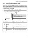
8.4.6 Timer 1 Data Register (TDR1)
The timer 1 data register (TDR1) is used to set the timer 1 value in the 8-bit mode of the
8/16-bit capture timer/counter or the interval timer value (interval timer function) or
counter value (counter function) of the higher 8 bits in the 16-bit mode.
■ Timer 1 Data Register (TDR1)
The values set in this register are compared with those set in the counter.
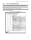
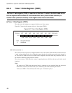
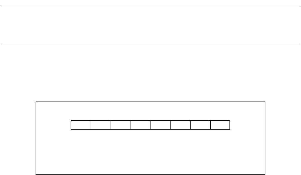
Figure 8.4-7 shows the bit structure of timer 1 data register (TDR1).
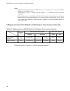
Figure 8.4-7 Timer 1 Data Register (TDR1)
● 8-bit mode (timer 1)
The values set in this register are compared with those set in the counter. When the interval timer function
is used, an interval timer value is set. When the counter function is used, the count value to be detected is
set. The values in TDR1 are reset in (loaded to) the comparator data latch when they match the values in
the counter or when the count operation is started.
The values written to TDR1 when the counter is operating become valid from the next cycle (after match
detection).
Note:
The values set in TDR1 when the interval timer is operating can be calculated from the expression
shown below. However, the instruction cycle is affected by the clock mode and gear function.
Values set in TDR1 = interval time/(count clock cycle × instruction cycle) - 1
bit7 bit6 bit5 bit4 bit3 bit2 bit1 bit0
R/W R/W R/W R/W R/W R/W R/W R/W
R/W : Readable/Writable
X : Undefined
Address Initial value
001C
H
XXXXXXXX
B