


138 System Specifications
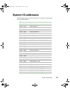
Memory map
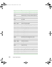
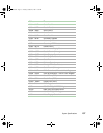
Interrupts
The following table suggests a logical interrupt mapping of interrupt sources.
It reflects a typical configuration, but you can change these interrupts. Use
the information to determine how to program each interrupt. The actual
interrupt map is defined using configuration registers in the I/O controller.
I/O Redirection Registers in the I/O APIC are provided for each interrupt
signal. The signals define hardware interrupt signal characteristics for APIC
messages sent to local APIC(s).
Address Range (hex) Amount Function
0 to 07FFFFh 640 KB DOS region, base system memory
0A0000h to 0BFFFFh 128 KB Video or SMM memory
0C0000h and 0DFFFFh 128 KB Expansion card BIOS and buffer
area
0E0000h to 0FFFFFh 128 KB System BIOS
0E0000h to 0EFFFFh 2 MB Extended system BIOS
FC000000h to FFFFFFFFh 64 MB PCI memory space
Important If you disable either IDE controller to free the interrupt for
that controller, you must physically unplug the IDE cable
from the system board. Simply disabling the drive by
configuring the SSU option does not make the interrupt
available.
Interrupt I/O APIC
Level
Description
INTR INT0 Processor interrupt
NMI N/A NMI from PIC to processor
IRQ1 INT1 Keyboard interrupt
Cascade INT2 Interrupt signal from second 8259
IRQ3 INT3 Serial port A or B interrupt from SIO device (you can
configure either)
IRQ4 INT4 Serial port A or B interrupt from SIO device (you can
configure either)
8508366.book Page 138 Tuesday, October 23, 2001 11:29 AM