


Functional Overview
10-2
HP DesignJets 1050C and 1055CM Printers Service Manual
Introduction
This Chapter contains a simplified description of the HP DesignJet
1050C/1055CM Printer circuits and mechanical functions.
Mechanical and printed Circuit Assembly (PCA) overviews present
a functional description of how the Printer operates.
HP DesignJet 1050C Printer
The HP DesignJet 1050C will have a network interface, 16 MB of
memory but will NOT include the Hard Disk Drive.
HP DesignJet 1055CM printer
The HP DesignJet 1055CM will have a network interface, 32 MB of
memory and a 2.1 Gbytes Hard Disk Drive. It will also be Postscript
ready.
Electrical System
The electrical system of the Printer consists of six major blocks and
their associated cabling:
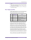
Power Supply Unit: Connected to the mains supply of whichever
country this block provides 24V, 5V, 3.3V and -15V to the rest of
the electrical system. It has a soft power switching feature
allowing the firmware to control when power is removed from
the system, and eliminates the need for high tension cables to the
front panel.
Main Electronics: This block contains the I/O, central processing
units and controls most of the motors and sensors in the printer.
The motors and sensors themselves are located throughout the
printer and are connected to the main electronics via cables.
Carriage: Connected to the printheads, this block supplies power
to them, as well as monitoring and protecting them from damage.
It also has the ability to control warming and to perform
continuity checking, as well as controlling the line sensor. The
carriage encoder is also located in this block.
Ink supply station: The Ink Supply Station is connected to the Ink
Cartridge supplies, and controls air pressure (pump, sensor and
valve), as well as monitoring ink levels and the supply latch