


Multiplexer Card
Numbers
The multiplexer card number depends on the switchbox configuration
(single-module or multiple-module) set for the multiplexers. (Leading
zeroes can be ignored for the card number.) For a single-module switchbox,
the card number is always 01.
For a multiple-module switchbox, the card numbers are 01, 02,...,n. The
switch module with the lowest logical address is always card number 01.
The card number with the next successive logical address is card number
02, and so on. See the HP B-size configuration guide for a definition of
logical addresses.
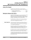
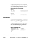
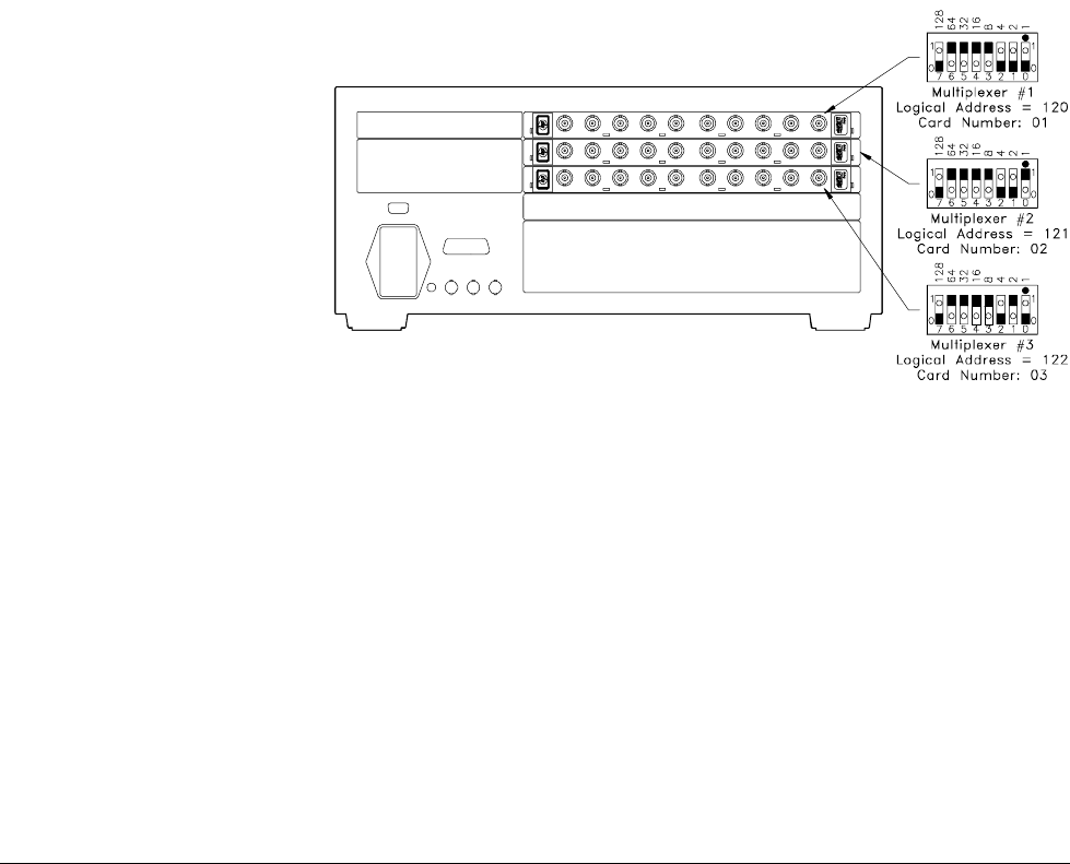
Example: Multiple-Module Switchbox Card Numbers
Assume the three multiplexers in the following figure form a
multiple-multiplexer switchbox instrument with multiplexer logical
addresses of 120, 121, and 122. Since card number 01 is assigned to the
module with the lowest logical address, etc., the card numbers are as shown.
Multiplexer Channel
Numbers
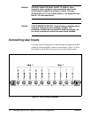
RF multiplexer channel numbers are 00 through 03 and 10 through 13.
The channels can be addressed using channel numbers or channel ranges.
For a single-module switchbox, channel ranges can span across the two
channel banks. For multiple-module switchboxes, channel ranges can
span across the channels of all modules.
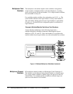
Figure 1-2. Multiple-Multiplexer Switchbox Instrument
14 Getting Started with the HP E1366A/E1367A RF Multiplexers Chapter 1