Appendix A
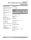
HP E1366A/E1367A RF Multiplexer
Specifications
Input Characteristics
Maximum Voltage - any center or shield
to any other center, shield, or chassis:
42 V Peak
Maximum Current per Channel or
Common:
1 Adc or ac
rms
Maximum Power per Channel or
Common:
24 W or 24 VA
General
Channels consist of non-latching
armature relays.
Typical Relay Life:
With no load: 5 x 10
6
operations
With max. rated load: 10
5
operations
Note: Relays are subject to normal wearout
based on the number of operations.
DC Performance
Thermal Offset:
<6µV
Typical Closed Channel Resistance:
<1Ω
End of Relay Life Closed Channel
Resistance:
<3Ω
Insulation Resistance
(any terminal to any terminal):
≤
(40° C, 65% RH): >10
8
Ω
AC Performance
For Z
L
= Z
S
= 50Ω (E1366A)
For Z
L
= Z
S
= 75Ω (E1367A)
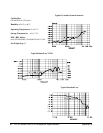
<10MHz <100MHz <500MHz <1.3GHz
Insertion Loss (dB)
≤(40°C, 65% RH)
<0.3 <0.7 <1.5 <3.0
Crosstalk(dB) (Channel-Channel*, or Channel-Common)
1
<-90 <-80 <-60 <-40
VSWR <1.2 <1.25 <1.35 <1.55
* With one channel closed.
1 Specification assumes 50Ω or 75Ω termination. If all channels
unterminated, derate specification by 6dB.
Risetime: <300psec
Signal Delay: <3nsec ± 50psec
Capacitance:
Center-shield <60pF
Chassis-shield <0.15
µF
Module Size/Device Type: B, register-based
Connectors Used: P1
Number of Slots: 1
VXIbus Interface Capability:
Slave, Interrupter, A16, D16
Interrupt Level: 1-7, selectable
Power Requirements:
Voltage +5 +12
Peak module current, IPM (A): 0.10 0.18
Dynamic module current, IDM (A): 0.01 0.01
Watts/Slot: 3.0
Appendix A HP E1366A/E1367A RF Multiplexer Specifications 61


