


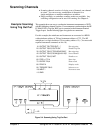

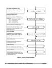
Scanning Channels
• Scanning channels consists of closing a set of channels, one channel
at a time. You can scan any combination of channels for a
single-multiplexer or multiple-multiplexer switchbox.
• Single, multiple, or continuous scanning modes are available. Any
switching configuration can be used for scanning. See Chapter 4.
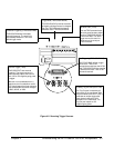
Example: Scanning
Using Trig Out Port
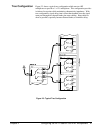
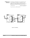
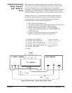
This example shows one way to synchronize instrument measurements of DUTs
with RF multiplexer channel closures. For measurement synchronization, the HP
E1300A/E1301A Trig Out BNC port is connected to the instrument External
Trigger In port. See the following figure for typical user connections.
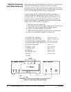
For this example, the mainframe and instrument are connected via HP-IB
with mainframe address of 709 and instrument address of 722. The RF
multiplexer is at logical address 120 (secondary address 15). (You must add
required instrument commands to line 10.)
10 OUTPUT 722;"TRIG EXT;...." ! Ext triggering
20 OUTPUT 70915;"OUTP ON" ! Enable Trig Out
30 OUTPUT 70915;"TRIG:SOUR BUS" ! Bus triggering
40 OUTPUT 70915;"SCAN (@100:103)" ! Scan channels
50 OUTPUT 70915;"INIT" ! Enable scan
60 FOR I=1 TO 4 ! Start loop
70 ENTER 722;A ! Enter result
80 PRINT A ! Display result
90 TRIGGER 70915 ! Advance scan
100 NEXT I ! Increment count
110 END
Figure 3-4. Scanning Using Trig Out Port
Chapter 3 Using the HP E1366A/E1367A RF Multiplexer Module 29