


Example: Scanning
Using "Trig Out"
and " Event In"
Ports
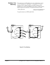
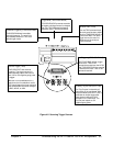
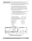
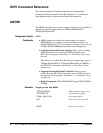
This example uses the HP E1300A/E1301A mainframe "Trig Out" and
"Event In" ports to synchronize RF multiplexer channel closures with an
external measurement device. See the figure below for typical user
connections. For this example, the mainframe and instrument are connected
via HP-IB with mainframe address of 709 and instrument address of 722.
The RF multiplexer’s logical address is 120 (secondary address =120/8 =15).
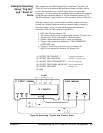
With this example, since synchronization with the computer cannot be
ensured, the external instrument must have internal memory capacity to
store the readings. Also, you must add the appropriate instrument
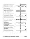
commands to line 10. The sequence of operation is:
1. INIT (line 50) closes channel 100.
2. The channel closure causes a trigger output from the "Trig Out" port.
3. Trigger to Ext Trig In starts channel 100 measurement.
4. Channel 100 measurement result is stored in instrument.
5. Trigger is then output from multimeter’s "MEASUREMENT
COMPLETE" port.
6. Trigger to "Event In" port advances scan to channel 101.
7. Steps 2-6 are repeated for channels 101 through 102.
10 OUTPUT 722;"TRIG EXT;..." ! Configure instrument
20 OUTPUT 70915;"OUTP ON" ! Enables "Trig Out" port
30 OUTPUT 70915;"TRIG:SOUR EXT" ! Event In triggering
40 OUTPUT 70915;"SCAN (@100:102)" ! Scan channels 00-02
50 OUTPUT 70915;"INIT" ! Enable scan
60 END
Figure 4-4. Scan Using "Trig Out" and "Event In" Ports
Chapter 4 Understanding the HP E1366A/E1367A RF Multiplexers 35