


Chapter 2
Configuring the HP E1366A/E1367A
RF Multiplexers
Using This Chapter
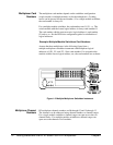
This chapter shows how to make user connections to the RF multiplexers
and how to configure the multiplexer modules. Chapter contents are:
• Warnings and Cautions . . . . . . . . . . . . . . . . . . . . . . . . . . . . . Page 17
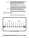
• Connecting User Inputs . . . . . . . . . . . . . . . . . . . . . . . . . . . . . Page 18
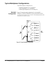
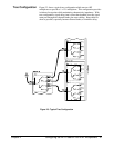
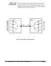
• Typical Multiplexer Configurations . . . . . . . . . . . . . . . . . . . Page 20
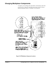
• Changing Multiplexer Components. . . . . . . . . . . . . . . . . . . . Page 23
Warnings and Cautions
Warning SHOCK HAZARD. Only qualified, service-trained personnel
who are aware of the hazards involved should install, configure,
or remove the RF multiplexers. Remove all power sources from
the mainframe and installed modules before installing or
removing a module.
Warning CHANNEL WIRING INSULATION. All channels that have a
common connection must be insulated so that the user is
protected from electrical shock in the event that two or more
channels are connected together. This means wiring for all
channels must be insulated as though each channel carries the
voltage of the highest voltage channel.
Caution MAXIMUM VOLTAGE/CURRENT. Maximum voltage between
any RF multiplexer center conductor or shield to any other
center conductor, shield, or chassis ground is 42 Vdc or 42 Vac
peak. Maximum current per channel or common is 1 A dc or
1 A ac RMS. Maximum switching power is 24 W or 24 VA per
channel or common. Maximum power per resistive termination
is 1 W or 1 VA. Exceeding any limit may damage the module.
Chapter 2 Configuring the HP E1366A/E1367A RF Multiplexers 17