


23
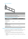
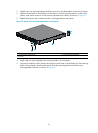
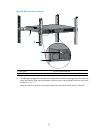
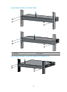
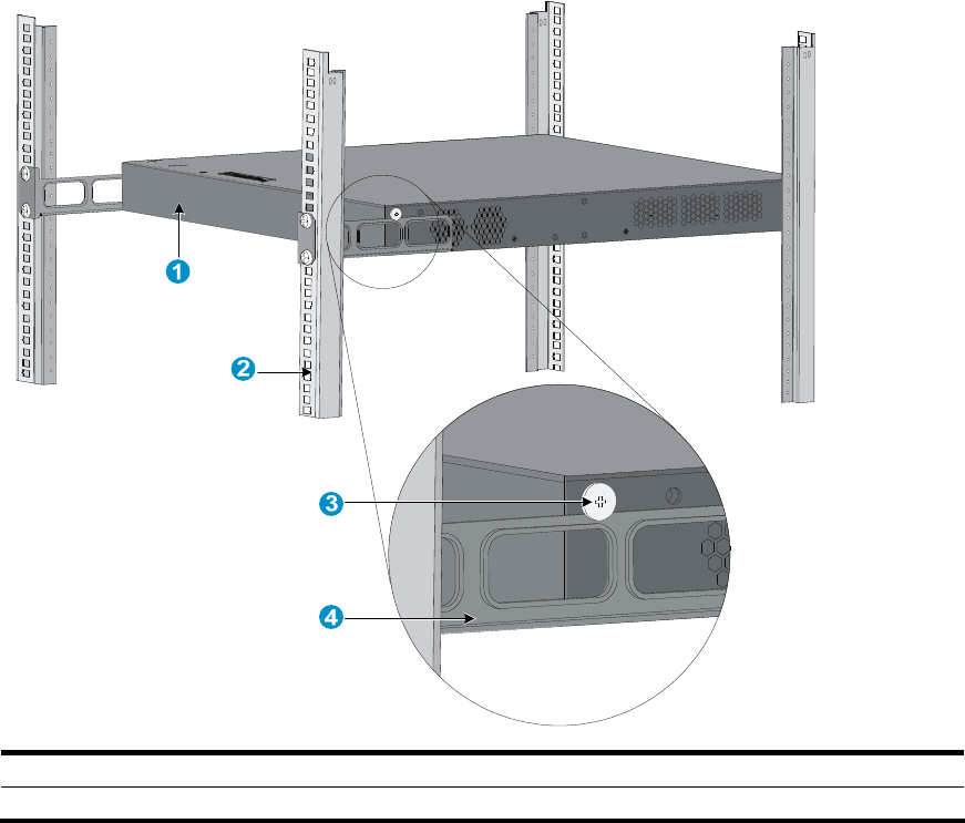
Figure 36 Mount the switch in the rack
(1) Rear panel (2) Rear square-holed post
(3) Load-bearing screw (4) Rear mounting bracket
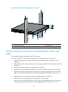
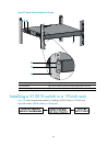
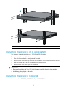
10. The other person aligns the oval holes in the front brackets with the mounting holes in the front rack
posts, and fixes the front mounting brackets with M6 screws (user supplied) to the front rack posts,
as shown in Figure 37.
Make su
re that front and rear mounting brackets have securely fixed the switch in the rack.