


40
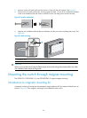
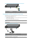
5. Connect the other end of the power cord to the RPS.
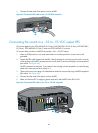
Figure 65 Connect the RPS cable to the +12 VDC RPS receptacle
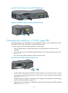
Connecting the switch to a –52 to –55 VDC output RPS
This section applies to the 5120-24G-PoE+ EI (2 slots), 5120-24G-PoE+ EI TAA (2 slots), 5120-48G-PoE+
EI (2 slots), 5120-48G-PoE+ EI TAA (2 slots) and 5120-24G-PoE+ SI switches.
To connect these switches to the RPS that provides –52 to –55 VDC output:
1. Wear an ESD-preventive wrist strap and make sure it makes good skin contact and is well
grounded.
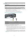
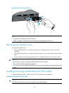
2. Unpack the RPS cable shipped with the RPS, identify the plug for connecting to the switch, correctly
orient the plug with the RPS receptacle on the switch chassis, and insert the plug into the receptacle
(see callout 1 in Figure 66).
The RPS receptacle is foolproof. If you cannot insert the plug into the receptacle, re-orient the plug
rather than use excessive force to push it in.
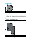
3. Tighten the screws on the plug with a flat-blade screwdriver to secure the plug in the RPS receptacle
(see callout 2 in Figure 66).
4. Connect the other end of the power cord to the RPS.
5. Make sure that the RPS is supplying power and verify that the RPS status LED is ON.
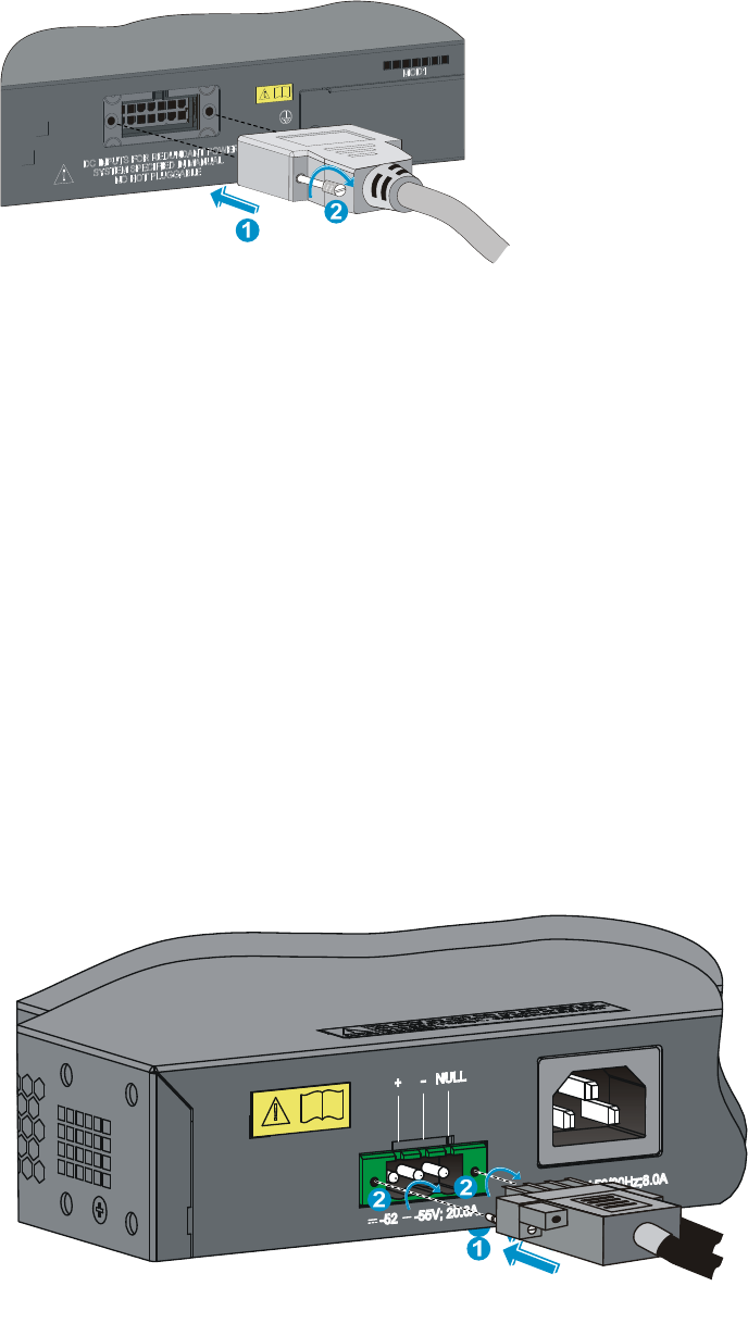
Figure 66 Connect the RPS cable to the –52 to –55 RPS receptacle
1
2
2