


57
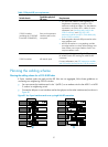
Table 12 Physical IRF port requirements
Switch chassis
Candidate physical
IRF ports
Requirements
5120 EI switches
(excluding the 5120-24G
EI and the 5120-48G EI)
Ports on the expansion
interface cards on the
rear panel
• You must order interface cards separately. For
long-distance connections, use XFP or SFP+
transceiver modules and fibers. For short-distance
connections, use CX4 or SFP+ cables. For more
information, see “Interface cards (only for the
5
120 EI switches)“ and “SFP/SFP+/XFP
tr
ansceiver modules and SFP+/CX4 cables (only
for the 5120 EI switches).”
• Ports assigned to the same IRF port must be on the
same interface card.
• All 5120 EI switches in a ring topology and the
non-edge switches in a daisy chain topology must
have at least one two-port interface card or two
one-port interface cards.
5120 SI switches All network ports
HP recommends that you use Gigabit SFP ports and
HP A3600 Switch SFP Stacking Kit cables for IRF
connection.
For more information, see “SFP transceiver modules
a
nd SFP Stacking Kit (only for the 5120 SI switches).”
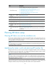
Planning the cabling scheme
Planning the cabling scheme for a 5120 EI IRF fabric
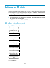
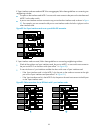
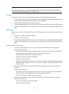
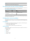
If 2-port interface cards are used and the IRF links are not aggregate, follow these guidelines on
connecting two neighboring 5120 EI switches:
• You can connect the interface card in slot 1 (MOD 1) on a member switch to the MOD 1 or MOD
2 card on its neighboring switch.
• Connect the left port on one interface card to the right port on the other interface card, as shown in
Figure 81.
Figure 81 Use 2-port interface cards to set up singl
e-link IRF connection