


55
Planning IRF topology and connections
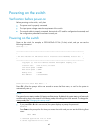
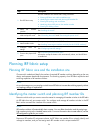
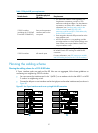
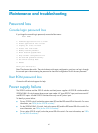
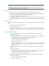
You can create an IRF fabric in daisy chain topology, or more reliably, ring topology. In ring topology,
the failure of one IRF link does not cause the IRF fabric to split as in daisy chain topology. Rather, the IRF
fabric changes to a daisy chain topology without interrupting network services.
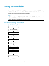
You connect the IRF member switches through IRF ports. An IRF port is a logical interface for the internal
connection between IRF member switches. Each IRF member switch has two IRF ports: IRF-port 1 and
IRF-port 2. To use an IRF port, you must bind physical ports to it.
When connecting two neighboring IRF member switches, you must connect the physical ports of IRF-port
1 on one switch to the physical ports of IRF-port 2 on the other switch.
You can bind several physical ports to an IRF port to create an aggregate IRF link for increased
bandwidth and availability.
NOTE:
• Figure 77 an
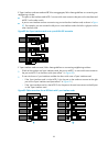
d Figure 78 show the topologies of a 5120 EI IRF fabric. Figure 79 and Figure 80 show the
topologies of a 5120-24G SI IRF fabric.
• The IRF port connections in these figures are for illustration only, and more connection methods are
available.
Figure 77 5120 EI IRF fabric in daisy chain topology
IRF
fabric
Master
Slave
Slave
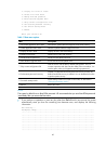
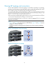
Figure 78 5120 EI IRF fabric in ring topology