


38
Connecting the power cord
WARNING!
Make sure that the grounding cable has been properly connected before powering on the switch.
Use Table 10 to identify the power cord connection procedures available for your switch.
Table 10 Power cord connection methods at a glance
Chassis Connection procedure
5120-8G SI
5120-16G SI
5120-24G SI
5120-48G SI
5120-8G-PPoE+ SI
5120-8G-PoE+ SI
5120-24G-PPoE+ SI
Connecting the AC power cord
5120-24G-PoE+ SI
AC-input:
Connecting the AC power cord
RPS input:
Connecting the switch to a –52 to –55 VDC output RPS
5120-24G EI (2 slots)
5120-24G EI TAA (2 slots)
5120-48G EI (2 slots)
5120-48G EI TAA (2 slots)
5120-24G EI
5120-48G EI
AC-input:
Connecting the AC power cord
RPS input:
Connecting the switch to a +12 VDC output RPS
5120-24G-PoE+ EI (2 slots)
5120-24G-PoE+ EI TAA (2 slots)
5120-48G-PoE+ EI (2 slots)
5120-48G-PoE+ EI TAA (2 slots)
AC-input:
Connecting the AC power cord
RPS input:
Connecting the switch to a –52 to –55 VDC output RPS
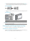
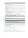
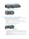
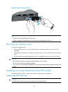
Connecting the AC power cord
To connect the AC power cord:
1. Wear an ESD-preventive wrist strap and make sure it makes good skin contact and is well
grounded.
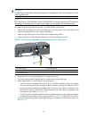
2. Connect one end of the AC power cord to the AC-input power receptacle on the switch.
Figure 62
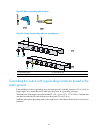
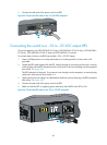
uses a 5120-48G EI switch for illustration, and Figure 63 uses a 5120-24G SI switch for
illustration.
3. Connect the other end of the AC power cord to the AC power outlet.