


31
Table 9 Models supporting wall mounting
Model Hole distance
5120-8P SI 98.5 mm (3.88 in)
5120-8G-PoE+ SI 174.0 mm (6.85 in)
5120-8G-PPoE+ SI 174.0 mm (6.85 in)
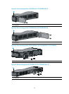
Introduction to wall anchor kit
NOTE:
No wall anchor kit is provided with the 5120 SI Switch Series.
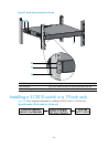
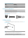
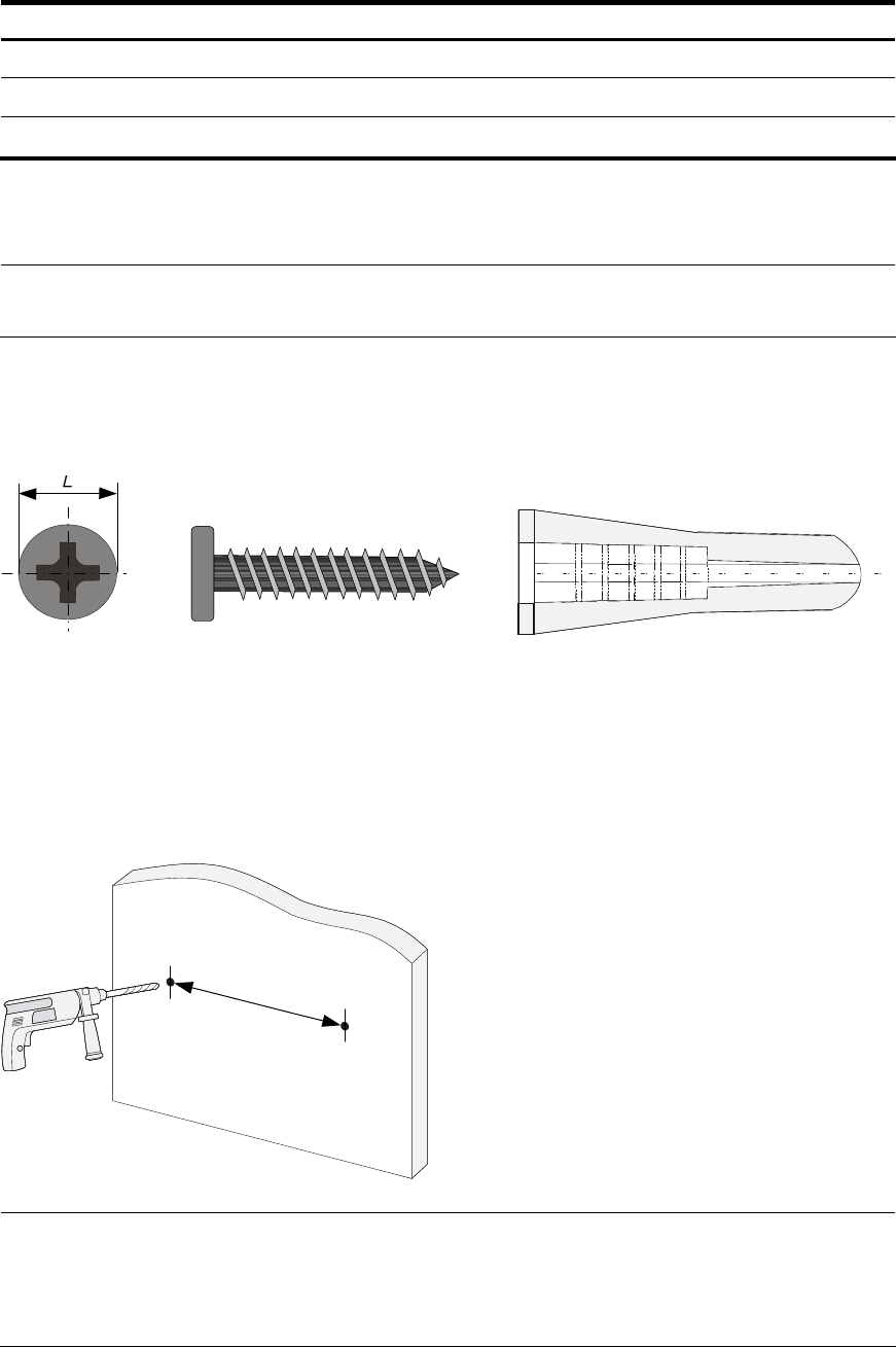
A wall anchor kit comprises an anchor and a screw, as shown in Figure 51. The screw must have an outer
diameter of no less than 4 mm (0.16 in) for wall mounting.
Figure 51 Wall anchor kit
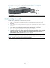
Installation procedure
To mount the switch to a wall:
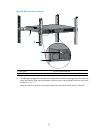
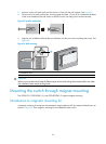
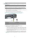
1. Drill two holes at the same height and X mm apart at the locations you marked. See Figure 52.
Figure 52 Hole distance
Xmm
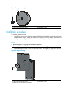
NOTE:
• The distance X between holes varies with devices. For specific distances, see Table 9.
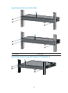
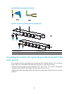
• Dr
ill holes according to the sizes of the anchors and screws so that the anchors can go into the holes
with
only the edges remaining outside, and the screws can be tightly fixed on the wall.