


32
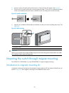
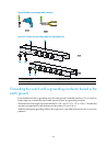
2. Insert an anchor into each hole until the anchor is flush with the wall surface. See Figure 53.
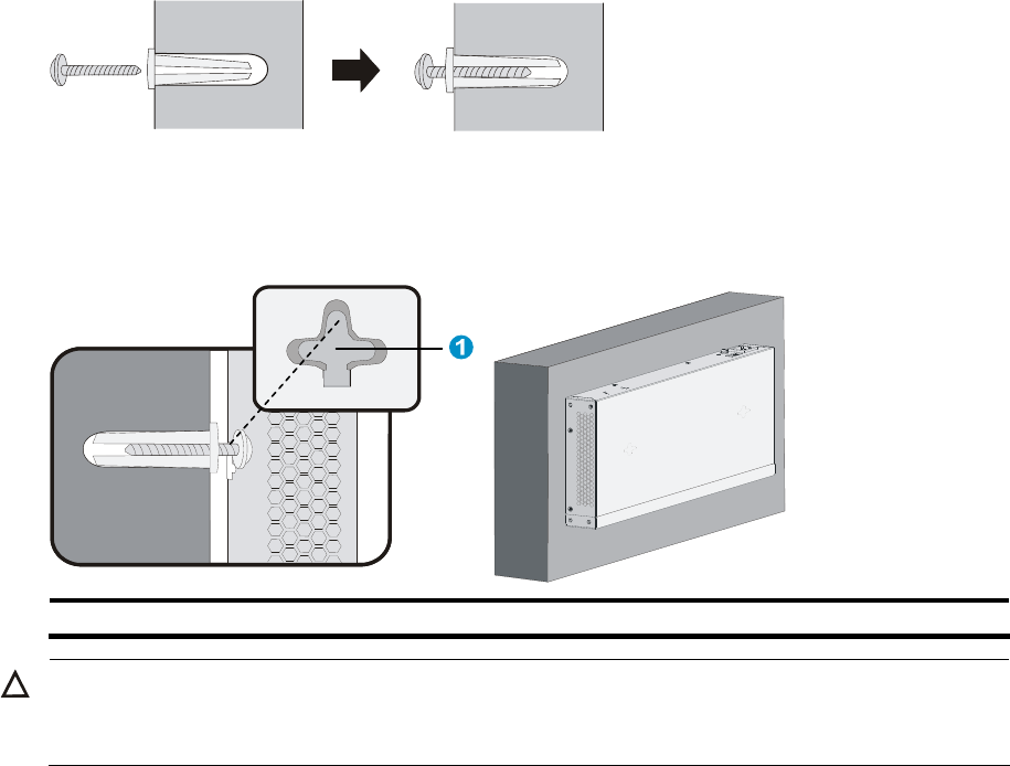
3. Drive a screw into each wall anchor, leaving a gap of at least 1.5 mm (0.06 in) between the base
of the screw head and the wall anchor so that the switch can hang on the screws securely.
Figure 53 Install a wall anchor
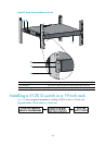
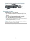
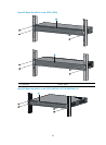
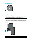
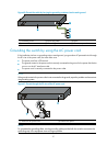
4. Align the two installation holes at the switch bottom with the two screws and hang the switch. See
Figure 54.
Figure 54 Wall mounting
(1) Installation hole
CAUTION:
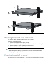
When you mount the switch, keep the Ethernet ports of the switch facing downwards and the two sides
with ventilation holes vertical to the ground.
Mounting the switch through magnet mounting
The 5120-8G SI, 5120-8G-PoE+ SI, and 5120-8G-PPoE+ SI support magnet mounting.
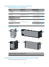
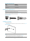
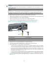
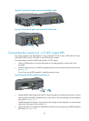
Introduction to magnetic mounting kit
A magnetic mounting kit comprises one permanent magnet and one M3*6 countersunk head screw, as
shown in Figure 55. F
our magnetic mounting kits are needed for each switch.