


35
WARNING!
Connect the
g
roundin
g
cable to the
g
roundin
g
system in the equipment room. Do not connect it to a fire
main or lightning rod.
NOTE:
The 5120 EI series, 5120-24G-PoE+ SI, and 5120-24G-PPoE+ SI switches come with an OT terminal
for
connecting to a grounding strip. For other switch models, you must prepare OT terminals yourself.
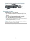
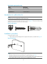
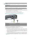
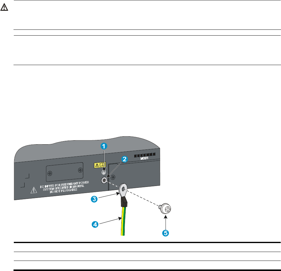
To connect the grounding cable, for example, to a 5120-48G EI (2 slots) switch:
1. Identify the grounding point (with a grounding sign) on the rear panel of the switch chassis, and
remove the grounding screw from the grounding point.
2. Attach the grounding screw to the OT terminal of the grounding cable.
3. Use a screwdriver to fasten the grounding screw into the grounding screw hole.
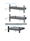
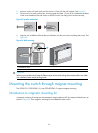
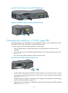
Figure 57 Connect the grounding cable to the grounding hole of the switch chassis
(1) Grounding sign (2) Grounding hole
(3) OT terminal (4) Grounding cable
(5) Grounding screw
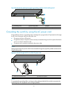
4. Remove the hex nut of a grounding post on the grounding strip.
5. Cut the grounding cable as appropriate for connecting to the grounding strip.
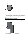
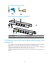
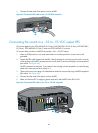
6. Make the connector for connecting to the grounding strip:
{ If an OT terminal is available, peel 5 mm (0.20 in) of insulation sheath by using a wire stripper,
and insert the bare metal part through the black insulation covering into the end of the OT
terminal, secure the metal part of the cable to the OT terminal with a crimper, cover the joint with
the insulation covering, and heat the insulation covering with a blow dryer to completely cover
the metal part (see callout A in Figure 58).
{ If no OT terminal is available, peel the insulation sheath as appropriate by using a wire stripper,
and bend the bare metal part into a ring (see callout B in Figure 58)
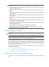
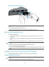
. Attach the OT terminal or
the ring to the grounding strip through the grounding post, and fasten it with the removed hex nut,
see Figure 59.