


78
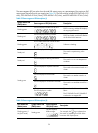
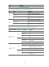
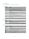
The seven-segment LED can also show the total PoE output power as a percentage of the maximum PoE
output power that a PoE switch can supply (see Table 24)
. The PoE switches include 5120-24G-PoE+ EI (2
slots), 5120-24G-PoE+ EI TAA (2 slots), 5120-48G-PoE+ EI (2 slots), and 5120-48G-PoE+ EI TAA (2 slots).
Table 23 Seven-segment LED description (I)
System status LED
(PWR) status
Seven-segment LED (Unit) status Description
Flashing green
The LED displays numbers one by one.
POST is running, and the LED displays
the ongoing test item ID.
Flashing red
The LED displays flashing numbers.
POST has failed, and the LED flashes
the ID of the failed test item.
Flashing green
A bar rotates clockwise around the LED.
Software is loading.
Steady red
The LED displays a flashing F character.
The switch is experiencing a fan
failure.
Steady red
The LED displays a flashing t character.
The switch is in an over-temperature
condition.
The LED displays a capital C character.
The switch is the command switch in a
cluster.
The LED displays an S character.
The switch is a member switch in a
cluster.
The LED displays a lowercase c character.
The switch is a candidate switch for a
cluster.
Steady green
The LED displays a number.
The member ID of the switch in an IRF
fabric.
The 5120-24G EI and 5120-48G EI
switches do not support IRF.
Table 24 Seven-segment LED description (II)
Port mode LED
(Mode) status
System status LED
(PWR) status
Seven-segment
LED (Unit) status
Description
Flashing green (1
Hz) (PoE mode)
Steady green
The LED displays
different signs.
0 - 20
%
21 -40
%
41 -60
%
61 -80
%
81 -10
0
For example, the sign indicates that
the switch is outputting 0 to 20% of the
maximum PoE output power.