


26
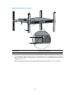
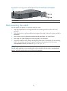
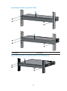
1. Identify the correct mounting position (see Table 8).
2. Align the round holes in one bracket with the holes in the mounting position.
3. Use screws to fix the mounting bracket to the chassis.
4. Repeat the preceding steps to attach the other mounting bracket to the chassis.
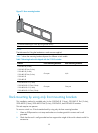
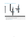
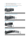
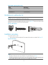
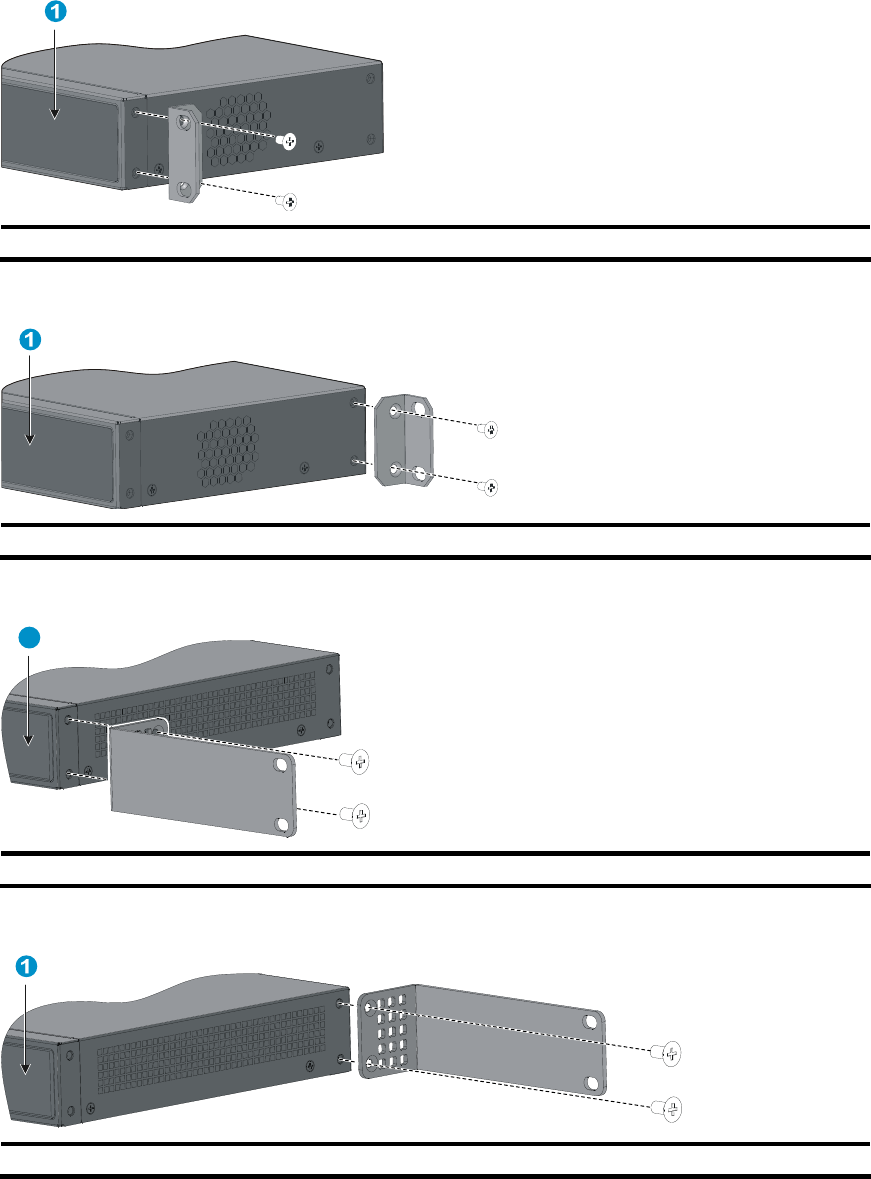
Figure 40 Front mounting position (5120-16G SI/5120-24G SI)
(1) Front panel
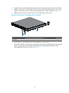
Figure 41 Rear mounting position (5120-16G SI/5120-24G SI)
(1) Front panel
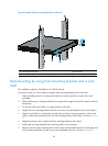
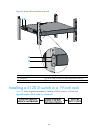
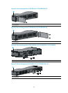
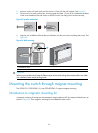
Figure 42 Front mounting position (5120-8G-SI)
1
(1) Front panel
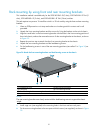
Figure 43 Rear mounting position (5120-8G-SI)
(1) Front panel