


25
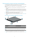
Mounting brackets and mounting positions
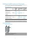
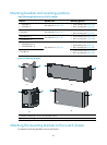
Table 8 Mounting brackets for the 5120 SI switches
Chassis Bracket view Mounting position
• 5120-16G SI
• 5120-24G SI
See callout A in Figure 39.
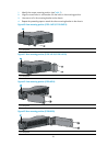
• Front mounting (see Figure 40)
• Rear mounting (see Figure 41)
5120-8G SI See callout B in Figure 39.
• Front mounting (see Figure 42)
• Rear mounting (see Figure 43)
5120-8G-PoE+ SI
5120-8G-PPoE+ SI
See callout D in Figure 39.
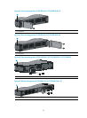
• Front mounting (see Figure 44)
• Rear mounting (see Figure 45))
• 5120-24G-PoE+ SI
• 5120-24G-PPoE+ SI
• Front mounting (see Figure 46)
• Mid-mounting (see Figure 47)
• Rear mounting (see Figure 48)
5120-48G SI
See callout C in Figure 39.
• Front mounting (see Figure 46)
• Rear mounting (see Figure 48)
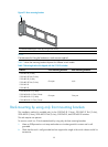
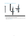
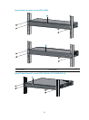
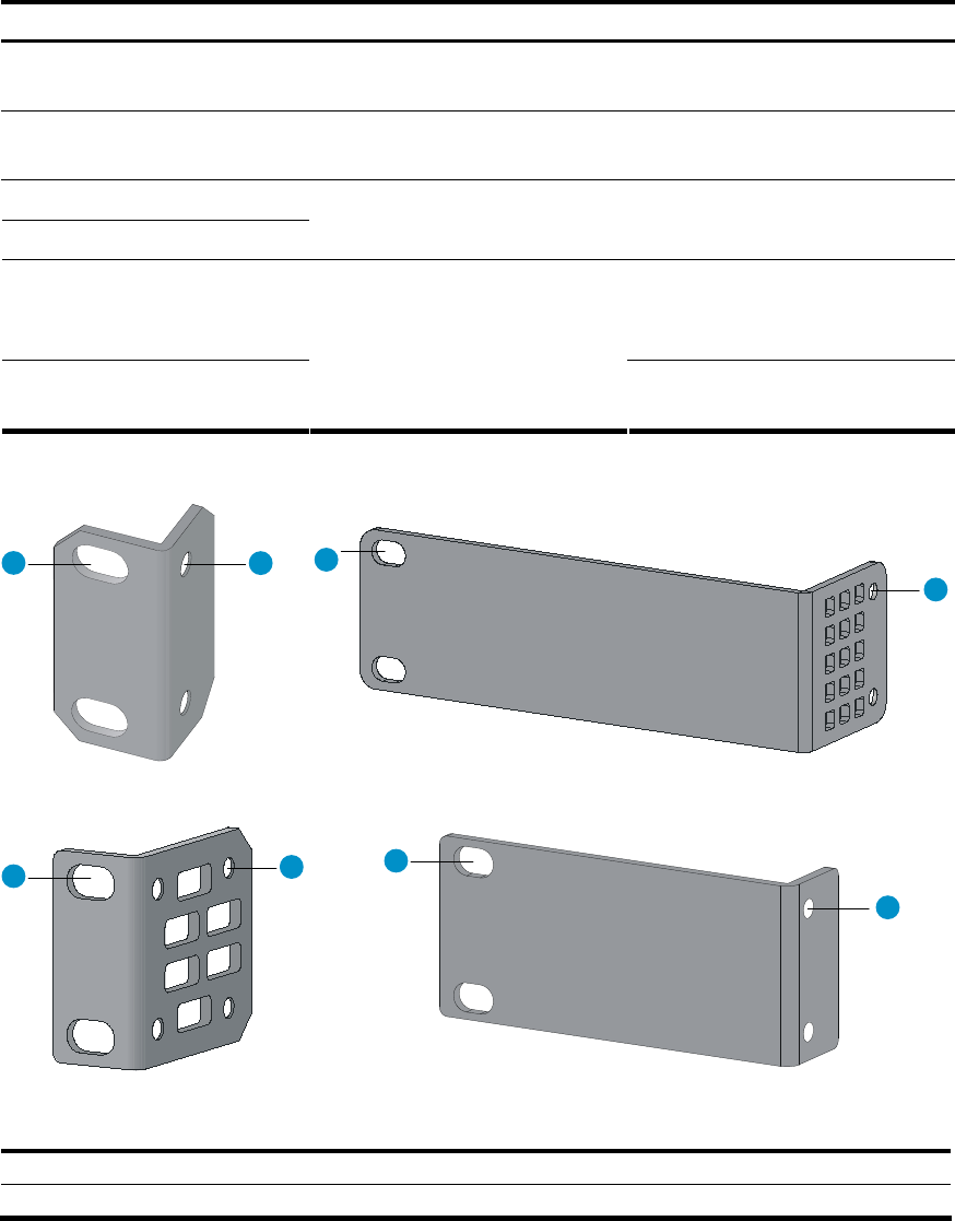
Figure 39 Mounting brackets
1 2
1
2
1
2
1
2
(A) (B)
(C)
(D)
(1) Holes for attaching to a rack (by using M6 screws)
(2) Holes for attaching to the switch chassis
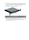
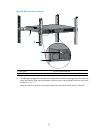
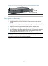
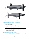
Attaching the mounting brackets to the switch chassis
To attach the mounting brackets to the switch chassis: