


SECTION 5: IPDS AND LAN DIAGNOSTICS, SETTINGS, AND FIRMWARE UPDATES
5-2
programmer to examine the content of the data and IPDS commands being sent to the printer.
5.1.1.1 Factory Reset Mode.
The Factory Reset Mode restores the IntelliBar AS Net IPDS interpreter parameters to their fac-
tory default values. Resetting to factory defaults clears all IPDS configuration settings that may
have been causing an error condition. Once the configuration settings are in a known state, you
will be able to correctly test and configure the IPDS interpreter.
The next time the printer is powered on, all parameters (for example, node name, serial port
speed, etc.) will be returned to the factory defaults. If you use this switch, don't forget to put it
back to the OFF position after the factory default settings have been restored.
Note: After a factory reset is performed, the TCP/IP address will be re-
set to the default value of 192.0.0.192. This address will have to be re-
configured before communications can be re-established with the host.
5.1.1.2 Set IPDS Active on Parallel Port Mode.
The IPDS Active on Parallel Port Mode enables the IntelliBar AS Net printer to accept IPDS
commands on its parallel communications port. This is useful for printing IPDS data when the
printer is attached to a terminal such as an IBM 5250 or for preparing the printer for a firmware
download.
5.1.1.3 Print Configuration Self-Test Settings Mode.
The Print Configuration Self Test Mode is useful for understanding the programmed state of the
IPDS interpreter and the print server. The Print Configuration Self Test Mode prints the current
default IPDS page size settings, IPDS and TCP/IP configuration settings, as well as, the ROM
version and checksum of the IPDS interpreter firmware. The Print Configuration Self Test is also
used to confirm that the IntelliBar print server and IPDS interpreter are operating correctly.
5.1.2 Configuring Diagnostic Functions Via the DIP Switches
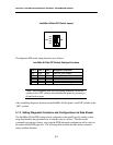
The diagnostic DIP switches are located on the rear of the printer directly above the RJ45
Ethernet socket.
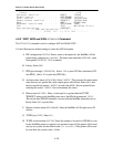
To enter the diagnostic mode, power up the printer and set DIP switch 4 to ON. The bi-color
IPDS Status Indicator LED will flash green indicating the printer is ready for setting of the dip
switches 1, 2, and 3 for diagnostic tests. After setting the appropriate switches for the desired
diagnostic function, set DIP switch 4 to the OFF position and the board will execute the selected
diagnostic function. The following illustration shows the DIP switch layout where switches 1 and
4 are ‘ON’ and switches 2 and 3 are ‘OFF.’