


Section 2
2-1
2 Communications Ports And Diagnostic Interfaces
This section describes the communications ports and user diagnostic interfaces for the IntelliBar
AS Net printer. The printer configuration and diagnostic functions are accessed through the front
control panel. Operation of these functions is covered in the main IntelliBar Users Guide. Com-
munications ports, Ethernet and IPDS status indicators and diagnostic DIP switches are located
on the rear panel of the printer. This Section discusses the rear panel functions.
2.1 COMMUNICATIONS PORTS
IntelliBar AS Net printers feature three host communications ports for network, parallel and serial
communications.
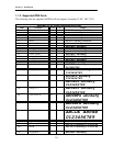
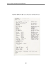
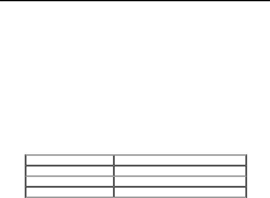
IntelliBar AS Net Communications Port Functions
Port Primary Function
Ethernet 10BaseT LAN Printing (IPDS + PCL + ASCII)
Centronics Parallel PC-share and down load IPDS firmware
RS-232 Serial PC-share / LAN share
2.1.1 Ethernet Communications Port. An RJ45 socket is provided for 10/100BaseT
network connection.
2.1.2 Parallel Communications Port. A standard 36-pin Centronics port is provided for
parallel communication from a PC or host terminal (ex., IBM 5250).
2.1.3 Serial Communications Port. An RS-232 DB nine-pin port is provided for serial
communications from a PC or a host terminal.
2.2 LED STATUS INDICATORS
2.2.1 Print Server Status Indicators.
Five vertically arrayed network LED status indicators (in ascending order Red, Green,
Yellow, Green, Yellow that respectively represent TEST/ERROR, LINK, XMIT, POL,
RCV) are located directly below the RJ45 Ethernet socket.
2.2.1.1 The red TEST/ERROR LED indicates the functionality of the IntelliBar print server. The
TEST/ERROR LED will light up during power on self-test when the printer is powered
on. If the TEST/ERROR LED stays constantly lit or blinks for more than once per sec-
ond, an error or fault condition is indicated.