


Chapter 6 Replacing Parts
99
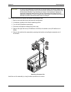
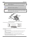
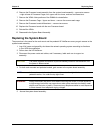
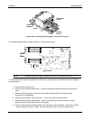
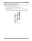
6. Remove the Processor board assembly from the system board assembly – remove ten screws
– eight at base of Processor Cages, four upper and four lower, and two at stiffener/strut.
7. Remove the VRMs. Note positions of the DIMMs for reinstallation.
8. Remove the Processor Cage – Upper and lower – remove four screws each cage
9. Remove the Processor board stiffener/strut – remove two screws
10. Replace the Processor board with the new Processor board.
11. Reinstall the VRMs
12. Reassemble the System Board Assembly.
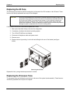
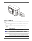
Replacing the System Board
The procedure is the same for the rack-mount and the pedestal HP NetServers once you gain access to the
system board assembly.
1. Log off all users and gracefully shut down the network operating system according to directions
in your NOS documentation.
2. Power down the HP NetServer.
3. Disconnect the power cords and cables, and if necessary, label each one to support re-
assembly.
CAUTION The power supplies will continue to provide standby current to the NetServer until
the power is disconnected.
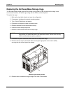
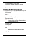
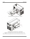
4. For both rack-mounted and pedestal models, gain access to the system board assembly.
NOTE In the rack-mounted version, this assembly is under the right side lower cover, in the
pedestal version, it is under the top right cover.
WARNING Always disconnect the power cords before removing the covers, to avoid exposure
to high energy levels that may cause burns when parts are short-circuited by metal
objects such as tools or jewelry. Disconnect any telephone cables to avoid exposure
to shock hazard from telephone ringing voltages.
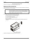
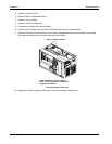
5. Access the system board assembly.