


Chapter 6 Replacing Parts
100
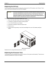
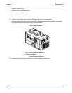
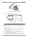
Processor
board
System
board
Cover
Captive
fastener
System Board Assembly showing System and Processor Boards
The system board provides the base support for the processor board.
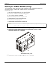
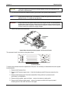
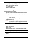
1A
1B
2A
2B
3A
3B
4A
4B
S1
DIMM
Slots
System Board
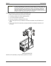
NOTE The system board includes a metal carrier tray. Do not remove the tray.
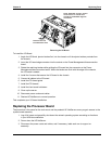
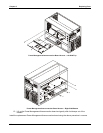
To access the system board for replacement of the part, it is necessary to disassemble the entire system
board assembly.
1. Remove the Processor fans
2. Remove the Processor cage covers – Undo the thumbscrew and lift the cover away from the
cage
3. Remove the Processor and Terminator assemblies. Note positions of processors and
terminators for reinstallation.
4. Remove the fan guides, upper and lower – remove two screws on each guide
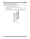
5. Remove the Processor cage support – remove two screws and slide the support upward
releasing the four tabs from the slots on the cages
6. Remove the Processor board assembly from the system board assembly – remove ten screws
– eight at base of Processor Cages, four upper and four lower, and two at stiffener/strut