


Chapter 2 System Information
30
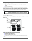
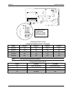
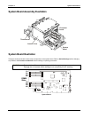
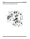
System Board Assembly Illustration
Processor
board
System
board
Access Cover
Thumbscrew
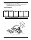
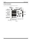
System Board Illustration
The figure shows the location of the major components on the system board. Refer to Switch Settings before changing
any switches and Processor Guidelines before installing or replacing processors.
CAUTION Some switches, if incorrectly set, may result in damage to system components.
Damage due to incorrect switch settings is not covered by the HP warranty.
1A
1B
2A
2B
3A
3B
4A
4B
S1
DIMM
Slots
System Board