iv HP OmniBook 2100/3000/3100
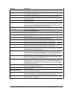
Figures
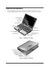
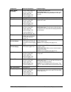
Figure 1-1. OmniBook - Front View....................................................................................................1-2
Figure 1-2. OmniBook - Side View.....................................................................................................1-2
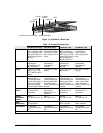
Figure 1-3. OmniBook - Back View....................................................................................................1-3
Figure 1-4. Replaceable Module Diagram......................................................................................... 1-14
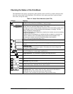
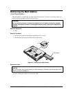
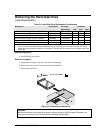
Figure 2-1. Removing the Main Battery ..............................................................................................2-3
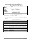
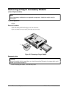
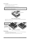
Figure 2-2. Removing a Plug-In Module .............................................................................................2-4
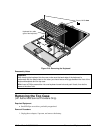
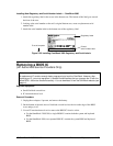
Figure 2-3. Removing the Hard Drive .................................................................................................2-5
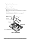
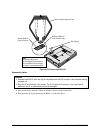
Figure 2-4. Installing a Hard Drive in the Case ...................................................................................2-6
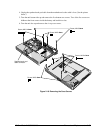
Figure 2-5. Removing the RAM Cover................................................................................................2-8
Figure 2-6. Removing a RAM Board...................................................................................................2-8
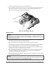
Figure 2-7. Removing the Hinge Covers and Icon Window Cover...................................................2-10
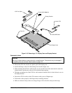
Figure 2-8. Removing the Icon PCA and Display Assembly.............................................................2-11
Figure 2-9. Removing the Hinge Covers and Icon Window Cover...................................................2-13
Figure 2-10. Removing the Display Bezel.........................................................................................2-14
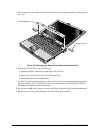
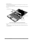
Figure 2-11. Removing the 12" LCD Module ...................................................................................2-15
Figure 2-12. Removing the 13" LCD Module ...................................................................................2-15
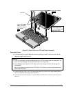
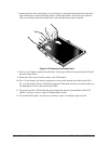
Figure 2-13. Removing a 12" Display Case and Display Bracket .....................................................2-17
Figure 2-14. Removing a 13" Display Case and Display Bracket .....................................................2-19
Figure 2-15. Removing the Hinge Covers and Icon Window Cover.................................................2-20
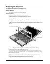
Figure 2-16. Removing the Keyboard................................................................................................2-21
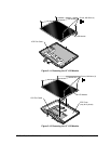
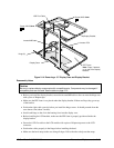
Figure 2-17. Removing the Heatsink .................................................................................................2-22
Figure 2-18. Removing the Case Screws ...........................................................................................2-23
Figure 2-19. Removing the Top Case ................................................................................................2-24
Figure 2-20. Two Types of CPU Modules and Thermal Kits............................................................2-25
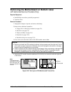
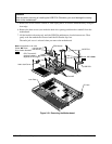
Figure 2-21. Removing the Motherboard...........................................................................................2-26
Figure 2-22. Installing OmniBook 3000 Regulatory and Serial Labels.............................................2-29
Figure 2-23. Removing a BIOS IC ....................................................................................................2-30
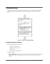
Figure 3-1. Basic Troubleshooting Steps.............................................................................................3-2
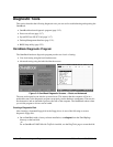
Figure 3-2. OmniBook Diagnostic Screens — Basic and Advanced.................................................3-12
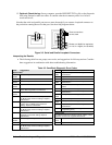
Figure 3-3. Serial and Parallel Loopback Connectors........................................................................3-14
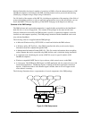
Figure 3-4. DMI Components............................................................................................................3-22
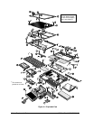
Figure 4-1. Exploded View..................................................................................................................4-2
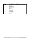
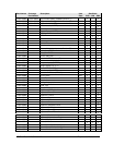
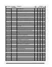
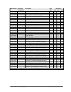
Tables
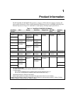
Table 1-1. OmniBook 2100/3000/3100 Models ..................................................................................1-1
Table 1-2. Product Comparisons..........................................................................................................1-3
Table 1-3. Activating Power Modes ....................................................................................................1-4
Table 1-4. Status Panel Indicators (Icon PCA)....................................................................................1-5
Table 1-5. Indicator Lights (Icon PCA and Battery)............................................................................1-6
Table 1-6. Function Keys (F1-F12)......................................................................................................1-6
Table 1-7. System Interrupts................................................................................................................1-8
Table 1-8. System Memory..................................................................................................................1-8
Table 1-9. System Input/Output Addresses (100-3FF) ........................................................................1-9
Table 1-10. DMA Channels.................................................................................................................1-9
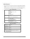
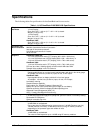
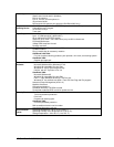
Table 1-11. HP OmniBook 2100/3000/3100 Specifications .............................................................1-10
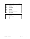
Table 1-12. HP OmniBook 2100/3000/3100 Accessories.................................................................1-12
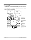
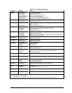
Table 1-13. Functional Structure........................................................................................................1-15
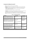
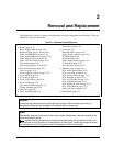
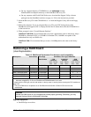
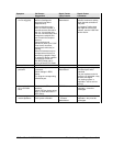
Table 2-1. Removal Cross-Reference ..................................................................................................2-1