


2-32 Removal and Replacement HP OmniBook 2100/3000/3100
Component Removal Procedures Additional Steps
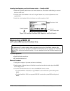
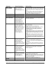
Cable, LCD flex
(13-inch display)
Plug-in module (page 2-4).
Display (page 2-9).
LCD module (page 2-12).
Reassembly Notes: The cable should protrude about
6 cm from the hinge. Secure the LCD flex cable to the
display bracket with a piece of Kapton tape near the
hinge.
Secure the LCD flex cable to the LCD module with a
piece of Kapton tape next to the LCD connector.
Caution: Use compatible parts (page 2-12).
Case, Bottom
See page 2-25.
Case, Display
See pages 2-16 and 2-18.
Case, Top
See page 2-21.
Cover, Audio Jack
Plug-in module (page 2-4).
Hard drive (page 2-5).
Display (page 2-9).
Keyboard (page 2-20).
Top case (page 2-21).
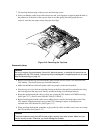
Motherboard (page 2-24).
Remove the motherboard only far enough to slip the
cover off the audio jacks.
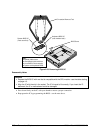
CPU Module
Plug-in module (page 2-4).
Hard drive (page 2-5).
Keyboard (page 2-20).
Note: If the CPU module is
held by two screws at its
front edge, also remove
these components:
Display (page 2-9).
Top case (page 2-21).
If the CPU module is held by two screws at its front
edge, remove them.
Unplug CPU module from motherboard.
Caution: Replace the CPU module with one of the
same type, and use a CPU thermal kit that is
compatible with the CPU module—see the table
starting on page 4-3.
Caution: Install both parts of a CPU thermal kit to the
new CPU. Stick the pad to the top of the CPU. Stick
the rubber spacer to the top back-right corner of the
board.
Caution: When installing the CPU module onto the
motherboard, press it down above the connectors—
but do not push on large components. Otherwise, you
could damage pressure-sensitive components on the
module.
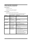
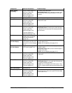
Fan
Plug-in module (page 2-4).
Hard drive (page 2-5).
Display (page 2-9).
Keyboard (page 2-20).
Top case, but only until the
heatsink is removed (page
2-21).
Reassembly Notes: Spread a thin layer of thermal
grease on the heatsink before installing the fan.
Place the vent in the side of the fan toward the side of
the heatsink.
Make sure the fan cable is positioned so it does not
interfere with contact points on the underside of the
heatsink.
Heatsink
Plug-in module (page 2-4).
Hard drive (page 2-5).
Display (page 2-9).
Keyboard (page 2-20).
Top case, but only until the
heatsink is removed (page
2-21).
Caution: Replace the heatsink with one that is
compatible with the CPU module—see the table
starting on page 4-3.
Hinge, Display
Plug-in module (page 2-4).
LCD module, but only until
the display bezel is
removed (page 2-12).
Reassembly Notes: Install the hinge so the slit in the
housing faces into the display case.
Caution: If the display is attached to the bottom case,
install one new hinge before you remove the other to
avoid stressing the cables.
Caution: Use compatible parts (page 2-12).
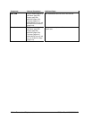
IC, BIOS
See page 2-29.
Keyboard
See page 2-20.