


HP OmniBook 2100/3000/3100 Removal and Replacement 2-31
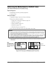
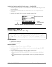
Removing Other Components
(HP Authorized Service Providers Only)
Required Equipment
• Small Phillips screwdriver.
• Pointed knife or probe (for display components).
• 5-mm hex driver (for bottom case components).
Removal Procedure
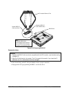
1. Unplug the ac adapter, if present, and remove the battery.
2. Remove the additional assemblies and follow the special steps indicated in the tables below.
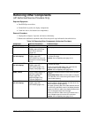
Table 2-8. Removing Other Components (Authorized Providers)
Component Removal Procedures Additional Steps
Bracket, Display
See pages 2-16 and 2-18.
Cable, Icon/MB
Plug-in module (page 2-4).
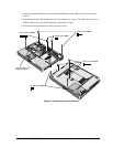
Display, but only until the
icon PCA is removed
(page 2-9).
The display does not have to be removed.
Cable, Inverter/MB
(12-inch display)
Plug-in module (page 2-4).
Display (page 2-9).
LCD module, but only until
the bezel is removed (page
2-12).
Reassembly Notes: The cable should protrude about
6 cm from the hinge.
Caution: Use compatible parts (page 2-12).
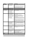
Cable, Inverter/MB
(13-inch display)
Plug-in module (page 2-4).
Display (page 2-9).
LCD module (page 2-12).
Display case (page 2-18).
Reassembly Notes: The cable should protrude about
6 cm from the hinge.
Secure the inverter/MB cable to the case near the
hinge area with a piece of Kapton tape.
Caution: Use compatible parts (page 2-12).
Cable, IR/Icon
Plug-in module (page 2-4).
Hard drive (page 2-5).
Display (page 2-9).
Keyboard (page 2-20).
Top case (page 2-21).
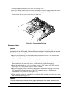
Remove the screws from the IR PCA and the speaker
bracket.
Reassembly Notes: Make sure the cable is clamped
by the bracket, and it routes through the bottom corner
of the window opening.
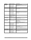
Cable, LCD flex
(12-inch display)
Plug-in module (page 2-4).
Display (page 2-9).
LCD module (page 2-12).
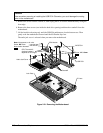
Reassembly Notes: The notched end of the metal
tube fits under the display bracket, and the tab on the
side fits inside the hinge opening.
The upper grounding tab of the cable attaches around
the hole for the left bezel screw in the display bracket.
Secure the LCD flex cable to the display bracket with a
piece of conductive tape near the hinge.
Secure the LCD flex cable to the LCD module with a
piece of Kapton tape next to the LCD connector.
Caution: Use compatible parts (page 2-12).