


HP OmniBook 2100/3000/3100 Removal and Replacement 2-33
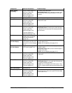
Component Removal Procedures Additional Steps
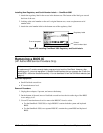
Latch, Display
(or Spring)
Plug-in module (page 2-4).
Hard drive (page 2-5).
Display (page 2-9).
Keyboard (page 2-20).
Top case (page 2-21).
To remove, lift the left corner.
Reassembly Notes: Put the spring on the latch shaft,
then insert the shaft through the bottom of the right-
hand slot.
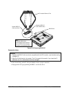
LCD module
See page 2-12.
Lens, IR
Plug-in module (page 2-4).
Hard drive (page 2-5).
Display (page 2-9).
Keyboard (page 2-20).
Top case (page 2-21).
Reassembly Notes: The lens should be flush with the
outside of the case.
PCA, Audio
Plug-in module (page 2-4).
Hard drive (page 2-5).
Display (page 2-9).
Keyboard (page 2-20).
Top case (page 2-21).
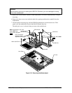
Motherboard (page 2-24).
Unplug audio PCA from underside of motherboard.
Reassembly Notes: Check that two rubber bumpers
are present on the new audio PCA directly behind the
two connectors.
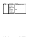
PCA, Icon
Plug-in module (page 2-4).
Display, but only until the
icon PCA is removed
(page 2-9).
The display does not have to be removed.
PCA, Inverter
(12-inch display)
Plug-in module (page 2-4).
LCD module, but only until
the bezel is removed (page
2-12).
Unplug the two cables and remove the inverter PCA
from the display case.
Caution: Use compatible parts (page 2-12).
PCA, Inverter
(13-inch display)
Plug-in module (page 2-4).
LCD module (page 2-12).
Unsnap the inverter PCA from the display case, then
unplug the cable.
Reassembly Notes: Make sure an inverter bumper is
installed on the PCA.
Caution: Use compatible parts (page 2-12).
PCA, IR
Plug-in module (page 2-4).
Hard drive (page 2-5).
Display (page 2-9).
Keyboard (page 2-20).
Top case (page 2-21).
Reassembly Notes: The IR PCA fits onto the pin on
the top case.
PCA, LVDS
Plug-in module (page 2-4).
Hard drive (page 2-5).
Display (page 2-9).
Keyboard (page 2-20).
Top case (page 2-21).
Unplug the LVDS PCA from the motherboard.
Reassembly Notes: Do not install the left screw until
you install the display assembly.
Caution: Do not overtighten the LVDS screws. They
fasten to a sheet-metal bracket and the threads could
strip.
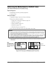
PCA, motherboard
See page 2-24.
PCA, Touch-pad
Plug-in module (page 2-4).
Hard drive (page 2-5).
Display (page 2-9).
Keyboard (page 2-20).
Top case (page 2-21).
Remove the 6 or 8 screws from the touch-pad support
plate and lift it off. Lift the touch-pad PCA and unplug
the flex cable from it.