


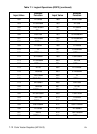
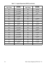
7-20 Color Vector Graphics (HP-GL/2) EN
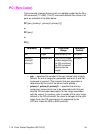
PP (Pixel Placement)
When printing, the printer places pixels at the intersection of the
squares of a theoretical, device-dependent grid covering the printable
area on a page. When the sides of two HP-GL/2 polygons touch each
other, the pixels along the border may be printed twice or not at all—
depending on the logical operation in effect. For example, if a source
rectangle consisting of all 1's is XORed with a destination consisting
of all 1’s, a white rectangle is printed. If another source rectangle is
placed on the page touching the first rectangle, the two rectangles are
white-filled except at their common border: that is, (1^1)^1 = 1.
To correct this situation, two models of pixel placement are used: grid
intersection and grid centered. The grid intersection model is the
default: pixels are rendered on the intersections of the
device-dependent grid covering the page. In the grid-centered model,
the number of rows and columns are each reduced by one, and pixels
are placed in the center of the squares, rather than at the
intersections.
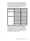
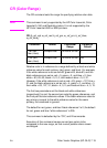
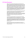
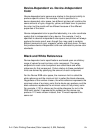
The following example illustrates the concepts of the two models.
Assume a rectangle extends from coordinate position (1,1) to position
(3,4). As shown below, for the same coordinates, the grid-centered
model produces a rectangle that is one dot row thinner and one dot
row shorter than the grid intersection model. Thus, when two or more
polygons on a page share a common border, grid centering (value=1)
can be turned on.
Since PCL printers print only at the intersections of the grid, the
actual implementation of the grid-centered model is also shown in the
following illustration.