


2-10 Using Color Modes EN
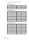
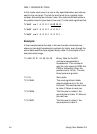
MODE 2: DIRECT BY PLANE
In this mode, a pixel is composed of three, one-bit components. The
data is transferred a plane at a time, one plane for each component.
Therefore, each bit in a plane represents one component of a pixel.
The underlined bits below show the components for a pixel.
Example:
In the example below the data in the row transfer commands are
shown in binary for clarity, even though the actual data would be
byte-aligned binary data. The example is for an eight-pixel-wide
image.
?*b#V row 1 plane 1 (red) b1 b1 b1 b1 b1 b1
?*b#V plane 2 (green) b2 b2 b2 b2 b2 b2
?*b#W plane 3 (blue) b3 b3 b3 b3 b3 b3
?*b#V row 2 plane 1 (red) b1 b1 b1 b1 b1 b1
?*v6W 00 02 01 01 01 01 Binary Data for the CID command
represented in hexadecimal. This
command sets the color space to
RGB, the PEM to Direct by Plane.
The palette size is ignored. The
last three bytes are always one
for this mode.
?*r1A Start raster
?*b1V10110000 Transfer plane 1 (the first bit for
each pixel in the first row). Each
bit controls the red primary.
?*b1V01110000 Transfer plane 2 (the second bit
for each pixel in the row). Each bit
controls the green primary.
?*b1W10101000 Transfer plane 3 (the third and
final bit for each pixel in the row)
and move to the next row. Each
bit controls the blue primary. Note
that the
?*b#W command is
used to send the last plane of
each row.