


EN The PCL Print Model 5-3
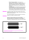
• Pattern Transparency Mode—The transparency or
opaqueness of the “white pixels” in the pattern (see the note
below). When set to 0 (transparent), these pixels have no
effect on the destination; when set to 1 (opaque), they are
applied through the black pixels of the source pattern to the
destination.
• Logical Operations—the Print Model uses logical operations,
such as AND, OR, XOR, and NOT when determining which
bits of the source, pattern, and texture become part of the
resulting image. The Logical Operations command (
?*l#O)
can vary the logical operation used, thus varying the outcome.
Note For RGB color images, “white” pixels are those for which all color
primaries are 255. For CMY color images, “white” pixels are those for
which all color primaries are 0.
For all rendering algorithms, white dots introduced in the dithering
process are not subject to transparency modes.
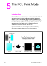
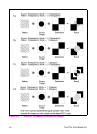
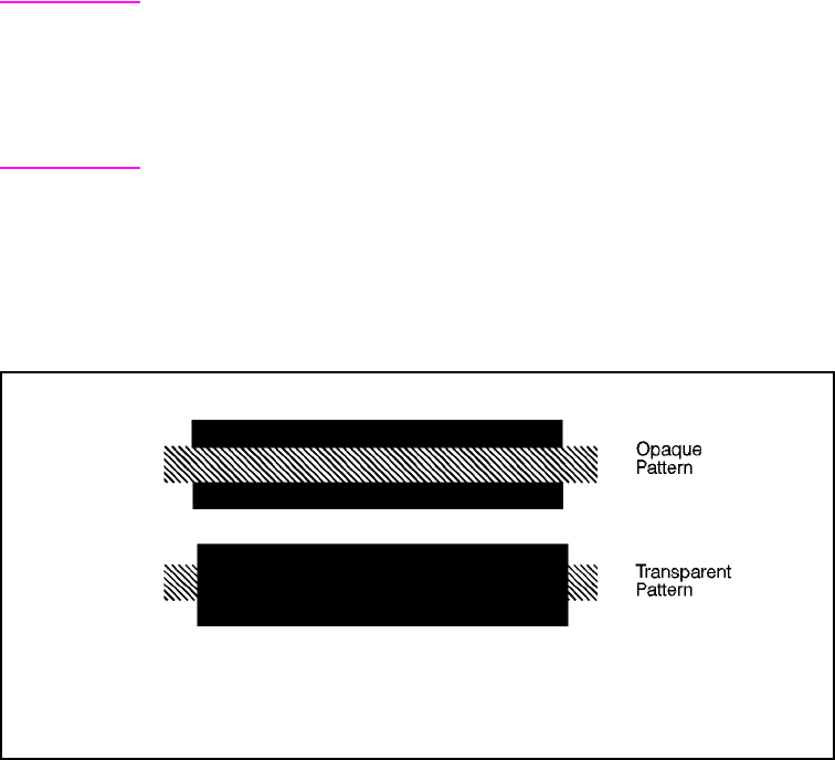
Figure 5-2 illustrates the effects of the source and pattern
transparency modes on the final image. (The transparency modes
work a little differently with rectangular area fill—see “Pattern
Transparency for Rectangular Area Fill” near the end of this chapter.)
Figure 5-2 Opaque and Transparency Modes
This example uses the default ROP. The output may appear differently
depending on the colors used.