


2-8 Using Color Modes EN
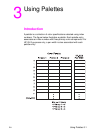
PEM 0: INDEXED BY PLANE
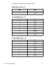
In Pixel Encoding Mode 0, successive planes of data are sent for
each raster row. A plane contains one bit for each pixel in a row. A
pixel is not fully defined until all the planes for that row have been
received, which is signaled by a transfer raster row command. The
planes in a row form index numbers into the current palette. For
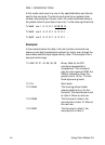
example, assuming three bits per index, the underlined column of bits
in the figure below is the palette index for pixel three of the first row (i1
is the least significant bit, i3 is the most significant bit). Note that the
Transfer Raster Data by Plane command (
?*b#V) is used for all
planes except the last plane of each row, which is sent using the
Transfer Raster Data by Row command (
?*b#W).
Example:
In the example below, the row transfer commands are shown in
binary for clarity, even though the actual data would be byte-aligned
binary data. The example is for an eight-pixel-wide image.
?*b#V row 1 plane 1 i1 i1 i1 i1 i1 i1
?*b#V plane 2 i2 i2 i2 i2 i2 i2
?*b#W plane 3 i3 i3 i3 i3 i3 i3
?*b#V row 2 plane 1 i1 i1 i1 i1 i1 i1
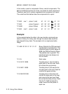
?*v6W 00 00 03 08 08 08 Binary data for CID represented
in hex. This command sets the
color space to RGB, the PEM to
Indexed by Plane, the palette size
to 8 (2
3
). The last 3 bytes are
ignored.
?*r1A Start raster.
?*b1V10110000 Transfer plane 1 (the first bit for
each pixel in the first row).
?*b1V01110000 Transfer plane 2 (the second bit
for each pixel in the row).
?*b1W10101000 Transfer plane 3 (the third and
final bit for each pixel in the row)
and move to the next row. Note
that the
?*b#W command is
used to send the last plane of
each row.