


Firmware
updates
IBM
will
periodically
make
firmware
updates
available
for
your
blade
server.
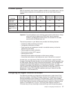
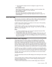
Use
the
following
table
to
determine
the
methods
you
can
use
to
install
these
firmware
updates.
Firmware
Update
diskette
RDM
Update
Xpress
Management-
module
Web
interface
Switch-module
Web
interface
Switch-module
Telnet
interface
Blade
server
BIOS
code
Yes
Yes
Yes
No
No
No
Blade
server
diagnostic
code
Yes
Yes
1
Yes
No
No
No
Blade
server
service
processor
code
Yes
Yes
Yes
Yes
No
No
1
You
must
set
up
a
custom
task.
Important:
To
avoid
problems
and
to
maintain
proper
system
performance,
always
make
sure
that
the
blade
server
BIOS
code,
service
processor
firmware,
and
diagnostic
firmware
levels
are
consistent
for
all
blade
servers
within
the
BladeCenter
unit.
The
service
processor
in
your
blade
server
provides
the
following
features:
v
Continuous
health
monitoring
and
control
v
Configurable
notification
and
alerts
v
Event
logs
that
are
timestamped,
saved
in
nonvolatile
memory,
and
can
be
attached
to
e-mail
alerts
v
Remote
graphics
console
redirection
v
Point-to-point
protocol
(PPP)
support
v
Remote
power
control
v
Remote
firmware
update
and
access
to
critical
server
settings
v
Around-the-clock
access
to
the
blade
server,
even
if
the
server
is
turned
off
At
some
time,
you
might
need
to
flash
the
service
processor
to
apply
the
latest
firmware.
Download
the
latest
firmware
for
your
blade
server
service
processor
from
the
IBM
Support
Web
site
at
http://www.ibm.com/pc/support/.
Use
the
BladeCenter
management-module
Web
interface
to
flash
the
service
processor.
The
Web
interface
is
described
in
the
IBM
Eserver
BladeCenter
Type
8677
Installation
and
User’s
Guide
on
the
IBM
BladeCenter
Documentation
CD
and
IBM
Eserver
BladeCenter
T
Types
8720
and
8730
Installation
and
User’s
Guide
on
the
IBM
BladeCenter
T
Documentation
CD.
Configuring
the
Gigabit
Ethernet
controllers
Four
Ethernet
controllers
are
integrated
on
the
blade
server
system
board.
Each
controller
provides
a
1000-Mbps
full-duplex
interface
for
connecting
to
one
of
the
Ethernet-compatible
switch
modules
in
I/O-module
bays
1
and
2,
which
enables
simultaneous
transmission
and
reception
of
data
on
the
Ethernet
local
area
network
(LAN).
Each
Ethernet
controller
on
the
system
board
is
routed
to
a
different
switch
module
in
I/O-module
bay
1
or
bay
2.
The
routing
from
Ethernet
controller
to
I/O-module
bay
will
vary
according
to
blade
server
type
and
the
operating
system
Chapter
2.
Configuring
the
blade
server
17