


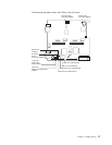
LED
locations
The
following
illustrations
show
the
LEDs
and
LED
power
switch
on
the
processor
board
and
I/O
board.
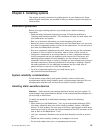
You
need
to
remove
the
blade
server
from
the
BladeCenter
unit,
open
the
cover,
and
press
one
of
the
Light
path
diagnostics
buttons
to
light
any
error
LEDs
that
were
lit
during
blade
server
operation.
These
LEDs
will
remain
lit
for
a
maximum
of
25
seconds.
See
“Light
path
diagnostics”
on
page
86
for
detailed
information
about
this
feature.
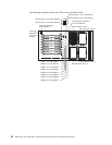
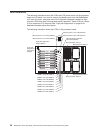
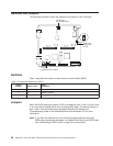
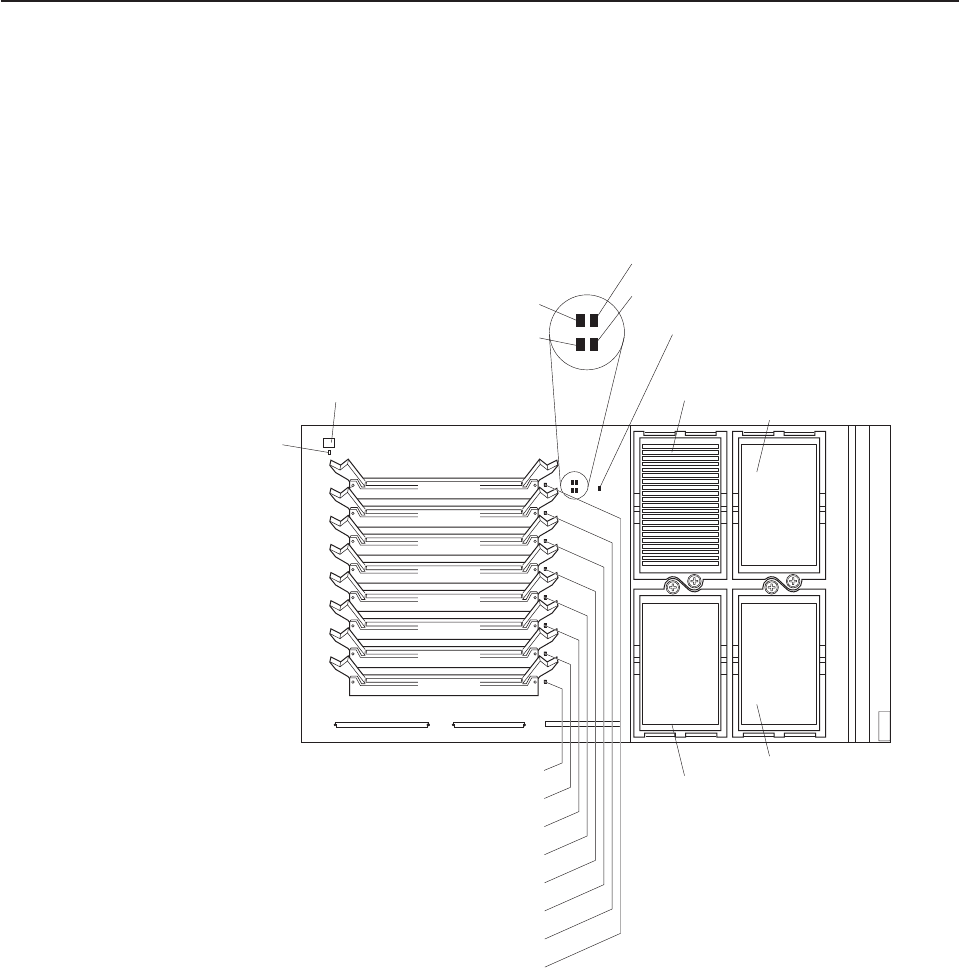
The
following
illustration
shows
the
LEDs
on
the
processor
board.
Microprocessor mismatch
error LED (DS5H3)
Light path diagnostics
button (SW9J1)
Light path
diagnostics
LED (green)
(DS9J1)
DIMM 1 error LED (DS6C1)
DIMM 2 error LED (DS6D1)
DIMM 3 error LED (DS6D2)
DIMM 4 error LED (DS6E1)
DIMM 5 error LED (DS6F1)
DIMM 6 error LED (DS6G1)
DIMM 7 error LED (DS6G2)
DIMM 8 error LED (DS6H1)
Microprocessor 2 error LED (DS5H4)
Microprocessor 1 error LED (DS5H5)
Microprocessor 3 error LED (DS5H1)
Microprocessor 4 error LED (DS5H2)
Microprocessor socket 3
Microprocessor socket 2
Microprocessor socket 4
Microprocessor socket 1
DIMM 1
DIMM 2
DIMM 3
DIMM 4
DIMM 5
DIMM 6
DIMM 7
DIMM 8
36
BladeCenter
HS40
Type
8839:
Hardware
Maintenance
Manual
and
Troubleshooting
Guide