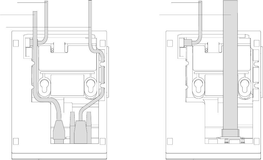
6. Connect any other signal cables for I/O devices to the correct ports.
7. Check that all signal cables are installed and seated in the correct ports.
8. If you are installing the printer on an integrated unit:
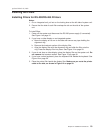
a. Pull out the locking lever at the left side of the system unit. (wide systems
only)
b. For single-station printers, place the printer in the square-shaped filler
panel.
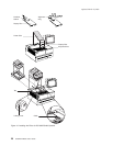
c. Route the keyboard cable to the side of the tab as shown in Figure 12 on
page 20.
d. Route all cables attached to the printer through the center opening of the
system unit and place the printer (with its filler panel, if it is a single-station
printer) on the system unit.
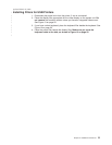
e. If you have fillers to install, go to “Installing the Fillers” on page 19.
f. Lift the system unit rear cover and attach any cables from the printer to the
system unit. (If this is a RS-232-attached printer, reattach the brick power
cord if you had to detach it to route it through the center opening.)
9. Power on the printer by either:
v Connecting the brick power supply cable to a properly wired and grounded
power source and powering it on
v Powering on the POS system unit for an RS-485-attached printer.
Note: Both voltage sources should not be connected to the printer at the
same time, even if one of the sources is powered off. Potential
system damage could occur under these conditions.
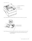
10. For single-station SureMark printers, turn on the power on/off switch on the
printer.
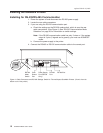
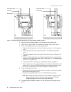
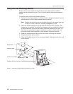
Cash drawer cable
Power cord
RS-232 cable
Cash drawer cable
RS-485 cable
Figure 7. RS-232 and RS-485 Cable Routing for Single-Station SureMark Printers
updated March 18, 2002
14 SureMark DBCS User’s Guide


