


19
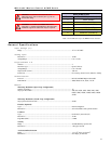
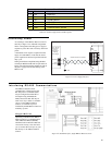
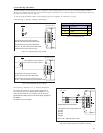
Connector P1
Pin # Flying Lead Function Description
1 White/Yellow I/O1 Open Collector I/O Point #1, +5 to +24VDC
2 White/Orange I/O2 Open Collector I/O Point #2, +5 to +24VDC
3 White/Violet I/O3 Open Collector I/O Point #3, +5 to +24VDC
4 White/Blue I/O4 Open Collector I/O Point #4, +5 to +24VDC
5 Green Analog Input 10 Bit, 0 to 5V Analog Input
6 Black GND Ground
7 Red +V +12 to +48 VDC Power Supply Input
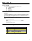
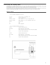
Section 2.1
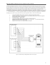
Interfacing the MDrive Motion Control
Section Overview
This section will acquaint the user with connecting and using the MDrive Motion Control.
!
Layout and Interface Guidelines
! Pin Configuration and Descriptions
! Interfacing Power
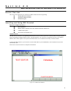
! Interfacing RS-485 Communications
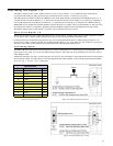
! Interfacing Digital I/O
! Interfacing Analog Input
Layout and Interface Guidelines
Logic level cables must not run parallel to power cables. Power cables will introduce noise into the logic level cables and make your
system unreliable.
Logic level cables must be shielded to reduce the chance of EMI induced noise. The shield needs to be grounded at the signal source
to earth. The other end of the shield must not be tied to anything, but allowed to float. This allows the shield to act as a drain.
Power supply leads to the driver need to be twisted. If more than one driver is to be connected to the same power supply, run
separate power and ground leads from the supply to each driver.
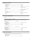
Recommended Wiring
The following wiring/cabling is recommended for use with the MDrive Motion Control:
Power
Belden Part# 9740 or equivalent 18 Gauge
Logic Wiring (I/O, Communications)
Wire Size .............................................................................................................. 20-22 AWG
General Practices
The following wire strip length is recommended:
Wire Strip Length................................................................................................. 0.250” (6.0 mm)
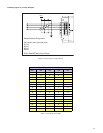
Pin Configuration and Descriptions
Table 2.1: P1 Pin Configuration and Description