


24
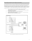
Interfacing Outputs
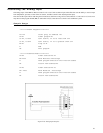
The MDrive Motion Control Outputs may be configured as either general purpose or set to one of two dedicated functions, Fault or
Moving. These outputs will sink up to 700 mA max and may be connected to +5 to +24VDC. Note that a current limiting resistor may
be required to limt the current to 700 mA.
As with the inputs the MDrive Motion Control Outputs may be used singularly or collectively as a group.
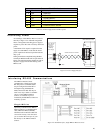
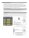
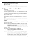
Interfacing a Single Output Examples
Figure 2.7: Output Interfaced to an LED
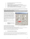
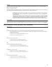
Figure 2.8: Output Interfaced to a Relay
PIN1
MDrive23 Motion Control
Sample Software Configuration #1: FAULT
S4=18,0 'Set IO4 to Fault, Active State=LOW
Sample Software Configuration #2: General Purpose
S4=16,0 'Set IO4 to General Purpose, Active State=LOW
+5 to +24 V
*External Resistor may be needed to
limit output sink current to 700mA
PIN1
MDrive23 Motion Control
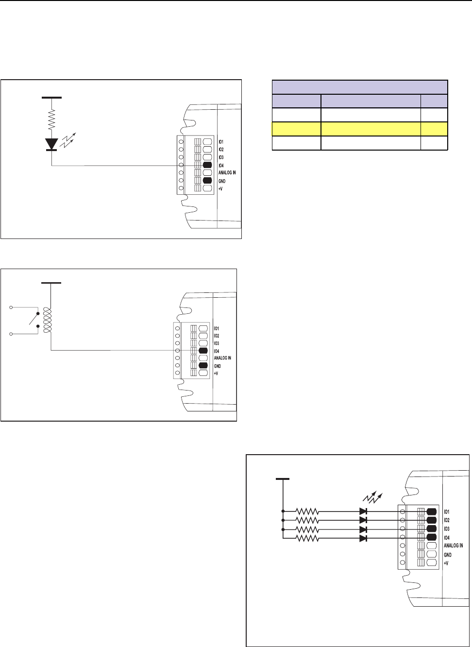
Sample Software Configuration
'set outputs to user outputs active low,
S1=16,0
S2=16,0
S3=16,0
S4=16,0
OT=<0-15> `Set outputs as 1 value
+5 to +24VDC
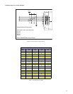
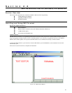
Figure 2.9: Outputs Interfaced to LED’s as a Group
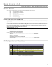
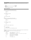
Input Functions
S<point>= Function Active
16 General Purpose 0/1
17 Fault 0/1
18 Moving 0/1
Table 2.5: Output Functions
Interfacing Outputs as a Group Example
To write to the outputs as a group the OT instruction is
used. This will give you a binary output of 0000 to 1111
from a decimal entry of 0-15. Output 1 will be the Least
Significant Bit (LSB), Output 4 will be the Most Significant
Bit (MSB).
See Table 2.4 for Truth Table.
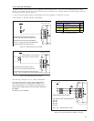
PIN1
MDrive23 Motion Control
Sample Software Configuration #1: FAULT
S4=18,0 'Set IO4 to Fault, Active State=LOW
Sample Software Configuration #2: MOVING
S4=17,0 'Set IO4 to Moving, Active State=LOW
(LED will illuminate when Axis is moving)
+5 to +24 V