


2
Variables ............................................................................................................................................................................................................................30
Math Functions ..................................................................................................................................................................................................................31
Motion Commands.............................................................................................................................................................................................................31
I/O Commands ..................................................................................................................................................................................................................32
System Instructions..........................................................................................................................................................................................................32
Program Instructions .........................................................................................................................................................................................................32
Section 2.3: MDrive Motion Control Command Set Summary ............................................................................................................... 35
Setup Instructions, Variables and Flags .....................................................................................................................................................................................35
Miscellaneous Instructions, Variables and Flags ........................................................................................................................................................................35
Motion Instructions, Variables and Flags ....................................................................................................................................................................................35
I/O Instructions, Variables and Flags .........................................................................................................................................................................................36
Program Instructions, Variables and Flags.................................................................................................................................................................................36
Position Related Instructions, Variables and Flags ....................................................................................................................................................................37
Encoder Related Instructions, Variables and Flags ....................................................................................................................................................................37
Mathematical Functions..............................................................................................................................................................................................................37
Section 2.4: MDrive Motion Control Command Set .................................................................................................................................. 38
Appendix A: ASCII TABLE ................................................................................................................................................................................ 64
Appendix B: Error Codes ................................................................................................................................................................................. 65
List of Figures
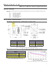
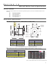
Figure 1.1 Rotary MDrive17 Motion Control Mechanical Specifications ..................................................................................................................................6
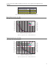
Figure 1.2 Rotary MDrive17 Motion Control 1713 Speed/Torque Data.....................................................................................................................................6
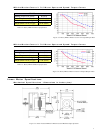
Figure 1.3 Rotary MDrive17 Motion Control 1715 Speed/Torque Data.....................................................................................................................................7
Figure 1.4 Rotary MDrive17 Motion Control 1719 Speed/Torque Data.....................................................................................................................................7
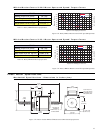
Figure 1.5 Linear Actuator MDrive17 Motion Control Mechanical Specifications .....................................................................................................................7
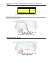
Figure 1.6 Speed-Force Curve - 24VDC (100% Current) .........................................................................................................................................................8
Figure 1.7 Speed-Force Curve - 45VDC (100% Current) .........................................................................................................................................................8
Figure 1.8 Rotary MDrive23 Motion Control Mechanical Specifications ................................................................................................................................12
Figure 1.9 Rotary MDrive23 Motion Control 2218 Speed/Torque Data...................................................................................................................................12
Figure 1.10 Rotary MDrive23 Motion Control 2222 Speed/Torque Data...................................................................................................................................13
Figure 1.11 Rotary MDrive23 Motion Control 2231 Speed/Torque Data...................................................................................................................................13
Figure 1.12 Linear Actuator MDrive23 Motion Control Mechanical Specifications ...................................................................................................................13
Figure 1.13 Speed-Force Curve - 24VDC (100% Current) .......................................................................................................................................................14
Figure 1.14 Speed-Force Curve - 45VDC (100% Current) .......................................................................................................................................................14
Figure 2.1 Power Supply Interface .........................................................................................................................................................................................20
Figure 2.2 RS-485 Interface, Single MDrive Motion Control ..................................................................................................................................................20
Figure 2.3 RS-485 Interface, Multiple MDrive Motion Control System ..................................................................................................................................21
Figure 2.4 Input Interfaced to a Switch ..................................................................................................................................................................................22
Figure 2.5 Input Interfaced to a PLC ......................................................................................................................................................................................22
Figure 2.6 TTL Interface to an Input Group ............................................................................................................................................................................23
Figure 2.7 Output Interfaced to an LED .................................................................................................................................................................................24
Figure 2.8 Output Interfaced to a Relay ................................................................................................................................................................................24
Figure 2.9 Outputs Interfaced tp LED’s as a Group...............................................................................................................................................................24
Figure 2.10 Analog Input Interface ...........................................................................................................................................................................................25
Figure 2.11 IMS Terminal Window .............................................................................................................................................................................................26
Figure 2.12 IMS Terminal Preferences ......................................................................................................................................................................................27
Figure 2.13 IMS Terminal Upgrader Window .............................................................................................................................................................................28
List of Tables
Table 1.1 Rotary MDI1713 Motor Specifications.....................................................................................................................................................................6
Table 1.2 Rotary MDI1715 Motor Specifications.....................................................................................................................................................................7
Table 1.3 Rotary MDI1719 Motor Specifications.....................................................................................................................................................................7
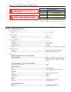
Table 1.4 Linear Actuator MDrive17 Motion Control Motor Specifications ..............................................................................................................................8
Table 1.5 ACME Screws for Linear Actuator MDrive17 Motion Control ..................................................................................................................................9
Table 1.6 Rotary MDI2218 Motor Specifications...................................................................................................................................................................12
Table 1.7 Rotary MDI2222 Motor Specifications...................................................................................................................................................................13
Table 1.8 Rotary MDI2231 Motor Specifications...................................................................................................................................................................13
Table 1.9 Linear Actuator MDrive23 Motion Control Motor Specifications ............................................................................................................................14
Table 1.10 ACME Screws for Linear Actuator MDrive23 Motion Control ................................................................................................................................15
Table 2.1 P1 Pin Configuration and Description....................................................................................................................................................................19
Table 2.2 P2 Pin Configuration and Description....................................................................................................................................................................20
Table 2.3 Input Functions ......................................................................................................................................................................................................22
Table 2.4 I/O Group Truth Table .............................................................................................................................................................................................23
Table 2.5 Output Functions ...................................................................................................................................................................................................24
Table 2.6 Microstep Resolution Settings ...............................................................................................................................................................................51