


16 Datasheet
Electrical Specifications
..
All system bus outputs should be treated as open drain signals and require a high level source
provided by the V
CTERM
supply.
AGTL+ inputs have differential input buffers which use V
REF
as a reference level. AGTL+ output
signals require termination to V
CTERM
. In this document, “AGTL+ Input Signals” refers to the
AGTL+ input group as well as the AGTL+ I/O group when receiving. Similarly, “AGTL+ Output
Signals” refers to the AGTL+ output group as well as the AGTL+ I/O group when driving.
The Power Good (PWRGOOD) signal and Test Access Port (TAP) connection input signals use a
non-differential receiver with levels that are similar to AGTL+. No reference voltage is required for
these signals. The TAP Connection Output signals are AGTL+ output signals.
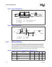
The Itanium 2 processor system bus requires termination on both ends of the bus. The Itanium 2
processor system bus supports both on-die and off-die termination controlled by two pins, TERMA
and TERMB. Please see the TERMA and TERMB pin description in Section 2.2.2.
The HSTL clock signals are the differential clock inputs for the Itanium 2 processor. The SMBus
signals and LVTTL power pod signals are driven using the 3.3 V CMOS logic levels listed in
Table 2-8 and Table 2-9, respectively.
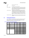
2.2.2 Signal Descriptions
Appendix A, “Signals Reference”contains functional descriptions of all system bus signals and
LVTTL power pod signals. Further descriptions of the system management signals are contained in
Chapter 6. The signals listed under the “Power” and “Other” group are described here:
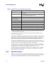
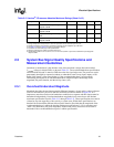
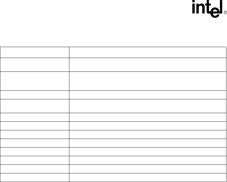
Table 2-1. Itanium
®
2 Processor System Bus Signal Groups
Group Name Signals
AGTL+ Input Signals BPRI#, BR[3:1]#, DEFER#, GSEQ#, ID[9:0]#, IDS#, RESET#
1
, RS[2:0]#,
RSP#, TRDY#
NOTES:
1. Signals will not be terminated on-die even when on-die termination (ODT) is enabled. See Intel
®
Itanium
®
2 Processor
Hardware Developer’s Manual for further details.
AGTL+ I/O Signals A[49:3]#, ADS#, AP[1:0]#, BERR#, BINIT#, BNR#, BPM[5:0]#
1
, BR0#,
D[127:0]#, DBSY#, DEP[15:0]#, DRDY#, HIT#, HITM#, LOCK#, REQ[5:0]#,
RP#, SBSY#, STBN[7:0]#, STBP[7:0]#, TND#
AGTL+ Output Signals FERR#, THRMTRIP#, DBSY[1:0]#, DRDY[1:0]#, SBSY[1:0]#
Special AGTL+ Asynchronous
Interrupt Input Signals
A20M#, IGNNE#, INIT#, LINT[1,0], PMI#
Power Good Signal
1
PWRGOOD
HSTL Clock Signals BCLKn, BCLKp
TAP Input Signals
1
TCK, TDI, TMS, TRST#
TAP Output Signals
1
TDO
System Management Signals
1
3.3V, SMA[2:0], SMSC, SMSD, SMWP, THRMALERT#
Power Signals GND, VCTERM
LVTTL Power Pod Signals
1
CPUPRES#, OUTEN, PPODGD#
Other TERMA, TERMB, TUNER1, TUNER2, VCCMON, VSSMON