


Datasheet 35
Electrical Specifications
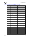
2.8 Recommended Connections for Unused Pins
Pins that are unused in an application environment (as opposed to testing environment) should be
connected to the states listed in Table 2-26. Pins that must be used in an application are stated as
such and do not have a recommended state for unused connection.
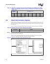
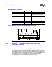
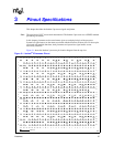
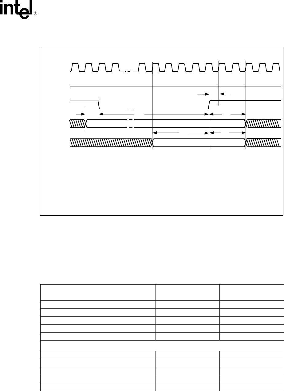
Figure 2-7. System Bus Reset and Configuration Timings for Warm Reset
000777b
BCLK
PWRGOOD
RESET#
Bus Ratio
(A[21:17]#)
T
A
= 1.15 ns minimum; (set up time to BCLK for deassertion edge of RESET#)
T
B
= 1 ms minimum for warm reset
T
D
= 2 BCLKs minimum, 3 BCLKs maximum
T
E
= 4 BCLKs minimum
T
F
= 2 BCLKs minimum, 3 BCLKs maximum
Additional
Configuration
Signals
T
B
T
D
T
E
T
F
T
A
t
1
t
2
t
3
T
C
T
C
= Bus ratio signals must be asserted no later than RESET#
t
-2
t
-1
t
0
t
-4
t
-3
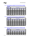
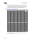
Table 2-26. Connection for Unused Pins (Sheet 1 of 2)
Pins/Pin Groups
Recommended
Connections
Notes
AGTL+ pins H
1,
2
HSTL Clock Signals Must be used
All Power Signals Must be used
PWRGOOD Must be used
TUNER[2:1] Must be used
TAP Signals
TCK L
1,
3
TRST# L
1,
3
TDI H
1,
3
TDO H
1,
3
TMS H
1,
3